|
Orifices
The amount of gas that can get into a burner is determined by the pressure of
the gas and the size of the hole it is trying to squeeze through. The size
of the hole is given most often by the size of the small bit used to drill it
although the real determination is the area of the hole. Dudley Giberson,
in his legendary catalog, gives recommended orifices for high pressure propane
for the burner heads that he sells. From a practical point of view, if
building a burner or modifying one to work from a different pressure or to
deliver more gas, the easiest solution is to have modest variety of numbered
bits in about the right range (say 55 to 70 in steps of 2 or 3 sizes) and use
the bits to first measure the existing hole then select one to enlarge it. As
mentioned below, these are very small bits and require a chuck that will go down
to 0.0 to hold them.
If drilling a cap for an orifice it is best to drill from the inside as brass
caps typically have a cone shape that centers the bit some what. If an
orifice is found to be too big, the hole can be braised or silver soldered (not
low temp soldered as sometimes the tip can get fairly hot) and drilled again.
If you are adjusting pressure with a regulator or a needle valve, it is possible
to make a range of orifice sizes work, but if the orifice is too small, the
maximum gas flow will be too low. If the orifice is too big, then the
velocity of the gas may not be enough to pick up air for a good mix.
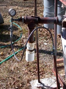
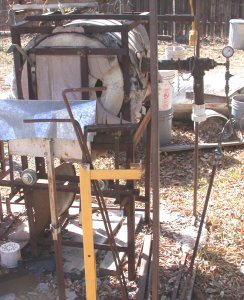
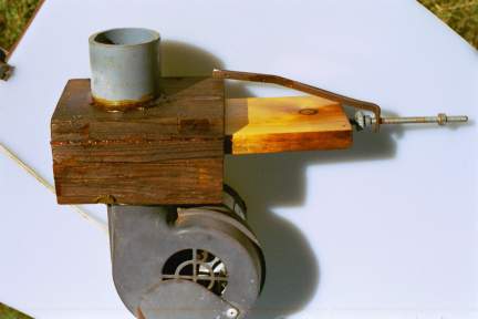
Another odd requirement is being able to see the adjustment with a gauge, like
the setup in the first picture on this page. If the
orifice is too big, then the back pressure will be so low that moving the needle
valve over a wide range produces a change from 4 psi to 3 psi. Making the
orifice just large enough so that at full pressure the right full gas flow
passes means that the gauge can be read from line pressure - say 12 psi - down
to 2-3 psi for idling. 2006-03-06 |
|
Other Burner Discussion
This page talks about home building burners. There are several
ways of making burners which are more complicated and therefore
are only for buying or for dedicated machinists.
VENTURI - A venturi burner uses a wasp waist shape to suck in
air with high pressure gas providing the power - in other words
it is a quality version of what is shown above. Of the greatest
importance is that the air flow is much more proportional to the
gas flow than the simple T pipe burner - increasing the gas flow
increases the air flow while coming reasonably close to
maintaining a constant proportion. The disadvantages of a venturi
is that there are limits to its range - too little gas and no air
is sucked in and too much gas means not enough air can fit
through the throat. The biggest advantage is that it requires no
electric power - as long as the gas flows, the flame will exist.
RIBBON - This is a term that is used for two different
burners, unfortunately. The older use of the term is for a shape
not unlike a pipe with a lot of holes drilled in one side. A
mixer sends a gas/air mix down the pipe and out the holes. In
tamer form these are used for heating BBQ's, ovens, etc. It
hotshot forms, it is used for softening a length of tubing for
bending in neon work.
Rather recently, it has been applied to a box of ceramic
material, molded rather complexly inside in the best versions, so
there are a lot holes on one side of the box and a pipe input on
the other. It is claimed to be much quieter, because of all the
small flames and more efficient. It is mostly used for glory holes
and must be built into the wall.
RECUPERATIVE - Here the fuel is injected into the preheated air at the last
instant, so the total design must reflect that fact. In a recuperative
design, the exhaust gases of the furnace heat the incoming air either directly
by having the outgoing passages and the incoming passages closely aligned and
the air separated from the exhaust by pipe walls or panels that will withstand
the heat or indirectly by having two piles of refractory heat storage (fire
bricks) one of which is heated by the exhaust while incoming air passed over the
previously heated other one - periodically the flows are exchanged. The
former is more commonly used on small studio furnaces, the latter on very large
industrial glass melters. The fuel is added to the heated air, which may
be 500F degrees or more, just at the last moment in an all refractory nozzle,
the air being driven by blowers located on the cool input side of the
recuperative unit. 2005-12-16
BURNER TUNING Notes
I went and looked at the Reil burner site and added a link to my
page. No, I don't think you can add a blower and the only reason
for considering it would be to save wasting the more complicated
hardware you have now.
The problem you having is common and has nothing to do with
"cooling the tip". If a burner is working properly, the
flame will stand just off the end, not heating the tip much at
all. Part of burner design is to create turbulence or other
complex flow at the end so the flame does not either blow off or
burn back. Reil's bragging about being able to keep the flame on
the burner with 25-30 pounds pressure is related to this. And it
is why he shows pictures.
1. If gas pressure is very low in a venturi burner (which is what
his burner and my T-type in back up mode are like) then the gas
can actually start burning at the nozzle with just the air right
there. Not good. Not efficient. May produce a noisy whistle.
2. With more gas pressure, the flame may be in throat where the
air and gas is mixing. This is very roaring noisy and soon the entire
burner body is glowing a bright red, not good.
3. With the beginning of proper pressure, the flame will be
inside the mouth of the burner (the bell on mine), will be
reasonably quiet and reasonably efficient. OK, but the bell gets
red.
4. As more air flow is provided, the flame moves out of the mouth
and stands at the end of the pipe, air being swept in past the
mouth keeping it centered and turbulent. Great.
5. Eventually, if the fuel flow is increased beyond the capacity
of the burner, the flame will start standing clear of end and it
becomes unstable. In open air, the flame will literally blow off
the burner
What happens if the pressure is too low for the size of the
burner is that the flame works it way back down the list, trying
to burn inside the pipe, etc. That is the pop pop. When you
turned up the pressure and the flame moved out of the pipe, it
was far enough out that it did not overheat the tip - no redness, lower noise.
If there is back pressure - not enough outflow from the forge/furnace
- then the flame gets shorter and also starts to work back
through the 5 steps.
|
BURNER BOOK REVIEW
I have been sent a book on burners [Gas Burners for Forges, Furnaces, &
Kilns, Michael Porter, Skipjack Press, Ocean Pines MD 2004, ISBN 1-879535203] to
review. My overall reaction was positive at first, but I am rather more
neutral on further reading. It took me a while to figure what was going
on. At first I thought it gets a bit too
focused on the particular design promoted in the book, which is built around
using predrilled MIG and torch welding tips to produce a long narrow nozzle point.
After rereading, I found that the structure hides confusion. There
is a good drawing of parts and the whole and a complete numbered parts list with
matching numbers on the drawing. But as construction develops, it turns
out that two parts have the same number and most parts have three names - the
piece name (MIG tip), the group name within the burner (adjustable tip) and the
major subpart within the burner (accelerator). Because a part number is
assigned to the first name - we can have a sentence like this on page 42 "Screw
the second contact tip into the other inverted female nut." Because the female
nuts are assigned part 13, there is no good way of telling them apart, although
they end up looking different after grinding.
Part of being too focused is failing to describe burners to begin with.
My father used to teach experienced workers how to be teachers of their skill to
new workers and one exercise he did was to take the teacher through the process
of getting up, going to the door, and turning the handle - but doing it
step-by-step without telling in advance what the overall goal was to be.
Most adults want to fit their learning into their previous experience, so they
want a framework or outline of the subject. This book launches with a
description of some complicated parts without sketching the system they fit in.
Beginning with safety is a good idea and starting with a hand torch that can be
used to build the other burners and, with a temporary mount, can be used to
build itself is a terrific sequence. I see nothing wrong with the burner
design although the fact that the orifices must each be built from scratch and
can not easily be drilled out means the design must be taken on faith. While the
use of a long thin tapering orifice clearly would increase the pickup of air, I
do question the importance the designer places on gas flow inside the nozzles.
Chapter 1 is Safety, Chapter 2 is The Burner System and Its Fuel and
Chapter 3 is Building the 1/2-inch Burner. (In total, there are 12 chapters,
footnotes, glossary, resources and index.) Logically, one would expect
Chapter 2 to draw the image of a burner system, mention the variations, and then
go into the details. It just goes into the details and is very good at
them. But I am sure someone with less experience with burners is going to
be bewildered. It is not even clear what the shape of the burners in this
book is going to be, much less how they fit in the design patterns of other
burners a novice or intermediate equipment builder might have seen.
Throughout the book, the author pays good attention to safety, making it
clear why propane tanks - which are used as shells for several of the projects -
must be treated with considerable care while opening them up.
All of the burners in the book are high pressure propane, induced air
flow, burners. Chapters 2, 3, 4, 7 & 8 are each devoted to the detailed
steps of building gradually increasing burners based on the nominal pipe size -
1/2 to 1-1/4 inch. They cover every single piece needed and how it is
drilled and assembled with good drawings and alternative choices in some cases.
Some of the parts are specialized and it will certainly help to use the
resources given, have a terrific junk bin, or know people who have cutoff
pieces.
Chapters 5, 6, 9, 10, and 11 are devoted to equipment that can use the
burners, starting with a forge (burner aimed down at a kiln shelf), then a forge
cart (burner aimed up), a foundry furnace (aimed horizontally), a farrier's
forge (smaller) and a glass furnace (a small unit that I have problems with.)
Chapter 12 covers braising. Among the differences between the units is how
various combinations of ceramic fiber, castable refractory, and Perlite enhanced
refractory are used, with good and given reasons for doing so. Depending
on the intensity of the flame and heat, the fiber is, in various units,
rigidized, and coated. The author really likes ITC #100, but as far as I
could find, never explains what it is, although on page 121, in a parts list it
is finally described as "infrared reflective coating". It is, in fact, a
fairly new product that has been discussed on glass forums with some question as
to how well it works. The book does mention that it is expensive.
Considering the detail the author goes into (for example, reminding
us to dry off a retractable measuring tape after using it as a dip stick to
measure water depth in a tank), I am particularly bothered by the design of the
foundry furnace. The lid hinge is built with one long arm that extends
beyond the pivot bolt. In a caption for a picture of the shape of the
parts, it is stated "It is not safe to use this extended hinge tab for a
handle." Considering how much the lid is going to weigh, I would
agree with that. But for the entire life of the unit, the long tab is
going to be sticking out the back - what is its use? I expected it would
be part of stop to keep the lid from falling back or a point to hang a
counterweight. In fact, its only purpose is to hold a short length of
chain with a pin on the end, keeping the pin far enough from the furnace to keep
it cool. The pin is used to hold the lid open angled over the lower pot.
So every time the furnace is to be accessed, someone is going to have to lift
the lid, reach around under the hot lid, get the pin and put it in the holes in
the hinge and later reach under the lid again to pull the lid out. I would
have been much happier with a design that built a stop into the hinge design so
that it could be opened from the front, not go too far and rest open. The
author likes that the pin allows the lid to be tilted over the hot chamber.
The glass furnace design begins with the disclaimer that using a home
made burner for a glass furnace is folly because it would not pass inspection so
this is really a small foundry and glory hole. In fact, the burner design
has little to do with inspection - the gas train, which is covered back in
chapter 2, being more important. The other furnaces seem to be more based
on experience, being mostly simple straight forward designs, while this one is
complicated - pivoting in its frame with an expectation that for some uses, the
frame will be filled with Perlite that will be removed for other uses.
Sorry, but I think a design like my Fire Hole, with a rectangular frame around
it so it can be set upright or horizontal is much easier than the pivot axle
arrangement.
As I look at the burner designs in review, the burners seem pretty
fragile across the air intake slots - there is a fair amount of weight hanging
off the intake on thin metal supports. There are, in fact, warnings about
torqueing the area when making connections. Since my blower based burners
are working reasonably well, I don't know if working through one of the designs
is something I want to do just to possibly disprove my doubts. 2004-03-29 |
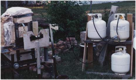
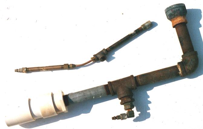
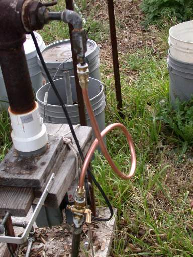
 I have built 6 or
8 burners with various sized pipe, from 1/4" to 1-1/2"
for various purposes. (See below.) I almost always build mine so
the gas is injected on one side of the top of the T and the air
is blown or sucked in the bottom. I try to build my blown burners
so that if the power fails the jet is located so as to suck in
enough air - using high pressure propane - to keep a reasonable
heat up. This involves moving the intake pipe to the right
position during construction. On an unblown burner, the same step
must be taken just to make it work. [I was asked where the air
comes from, since it seems closed, but when power fails, the
valve is open (as shown at right) and thus air enters the intake
of the blower, passes through the slots of the squirrel cage and
up the pipe. Some kinds of blowers - expensive - would not pass
air like this when stopped.]
I have built 6 or
8 burners with various sized pipe, from 1/4" to 1-1/2"
for various purposes. (See below.) I almost always build mine so
the gas is injected on one side of the top of the T and the air
is blown or sucked in the bottom. I try to build my blown burners
so that if the power fails the jet is located so as to suck in
enough air - using high pressure propane - to keep a reasonable
heat up. This involves moving the intake pipe to the right
position during construction. On an unblown burner, the same step
must be taken just to make it work. [I was asked where the air
comes from, since it seems closed, but when power fails, the
valve is open (as shown at right) and thus air enters the intake
of the blower, passes through the slots of the squirrel cage and
up the pipe. Some kinds of blowers - expensive - would not pass
air like this when stopped.]
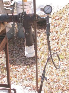
 Each
installation will be different. Burners should be fairly firmly mounted,
especially those which have white ceramic heads which are fairly fragile and
should be mounted with a half inch space between the head and the burner port.
My choice of mounts, used on both my furnace and glory hole, is to hang the
burner below a support bar that can be shifted for correct lineup but which is
unlikely to shift in normal use.
Each
installation will be different. Burners should be fairly firmly mounted,
especially those which have white ceramic heads which are fairly fragile and
should be mounted with a half inch space between the head and the burner port.
My choice of mounts, used on both my furnace and glory hole, is to hang the
burner below a support bar that can be shifted for correct lineup but which is
unlikely to shift in normal use.