|
Below, left to right, the framed hole standing on a larger frame holding
other hot stuff. In the first image the PVC to the right is where the
blower for the burner attaches. The lid is set to one side in one parking
position on fire brick. The center image shows the rain shield raised up
and the pole that supports two hooks. The lower hook catches the chain
from one side of the lid like a hinge or pivot - the chain runs from the lid in
the picture. The right image shows the lid hung by the other chain to the
upper hook, which I use so I don't need a layer of firebrick to lay it on.
2008-01-06

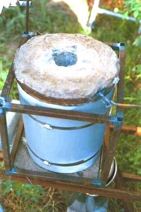
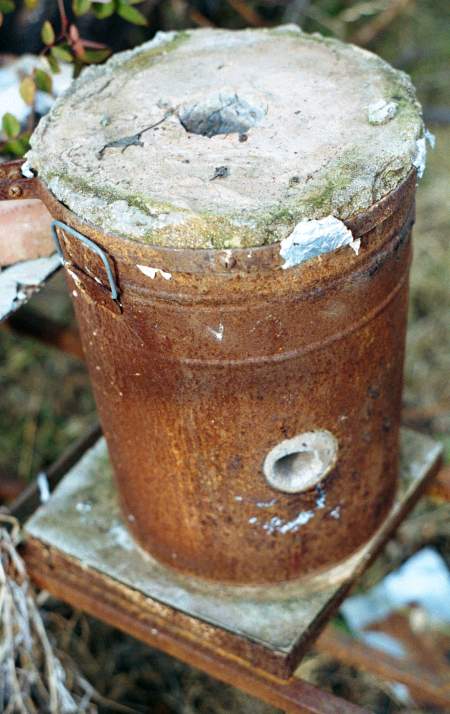
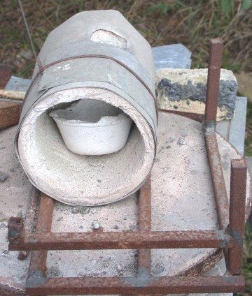
These 3 pictures show the hole with the lid in place and the large link chain
resting on top. The two chains are attached to the compression band around
the lid, one welded and the other to the tightening bolt. The center image shows
one of the crucibles in the open hole resting on firebrick to raise it near the
top. The heating flame comes in from the right rear behind the pot which
is centered when in use. The corner and centering pieces can be seen at the
bottom of the frame. Tools on right described below image. 2008-01-06
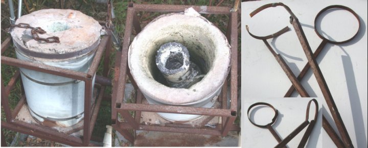
Tools for handling the foundry pot. The pot must be lifted
out straight up with a grip below the lip, the gripper having to fit between the
pot and the wall. The loop is set on a fire resistant surface (sand in the
casting pit) and the pot set inside the loop which is then lifted to pick up the
pot for pouring. The image shows one end in the main picture and the other
in the insert. The loops at
each end of 1/2" square tubing for different sized pots. The
clamps for lifting the pot had to be quickly adjusted to squeeze
between the walls of the hole and the pot. Note that they overlap
when closed for a smaller opening. I rebuilt [2003-10-30] the lifting tongs,
welding 1/2" square steel tubing to the straight sides for strength, still
keeping the bottom end thin. The original clamps were pretty weak
when lifting several pounds of molten brass that might splash on my legs.
BUILDING A FIREHOLE STEP BY STEP
- Read through directions first.
- NEEDED: Insulating Castable, sheet metal, plastic film, hose clamps,
scrap Styrofoam, steel flat stock, rod, trowel, mixing tools and containers,
support board, sheet metal screws, ruler.
- Buy 24 gauge sheet metal. The cheapest way if you have other uses is a full
sheet from a sheet metal (air conditioning) shop.
- Cut two sheets. The outer sleeve is 1/2" taller than the inner. My outer
is 14" tall. The ID is 8" and the OD 12"
- To determine the length, multiply the diameter by 3.5 or
4 (instead of 3.14159) so there is an overlap. [28-32" for the ID,
42-48" for the OD to match mine.]
- Buy 4 oversized hose clamps (or enough to go around the outside in two
locations, they will interconnect.)
- Use the clamps to form the inside sleeve, then hold the inside
sleeve with sheet metal screws installed from the inside. Remove the
clamps.
- Use the clamps to form the outside sleeve. Do not use screws
here to allow tightening later.
- Cut a piece of Styrofoam into a cylinder the size of the burner
head/tube and trim one end diagonally so the port will be tangential (or
nearly so) to the inside wall. Cut a matching hole in the outside
sleeve about halfway down, and insert the core. Secure the core with
glue or tape, etc. during assembly. Core does not penetrate inner sheet
metal, just outer.
- On a flat board (plywood) mark an X for centering and draw circles (4 or
more)
from just inside the ID to just outside the OD. Lay clear plastic film
over the board.
- Place the sleeves on the plastic, centering as needed. You may
wish to take a small amount of insulating castable and make spacers - about
2" cubes - to keep the sleeves evenly separated.
- Make a rather stiff mix of enough insulating castable to put about 2" in
the bottom of the space between the two shells. Drop it into the
space, gently, working around the slot. Check the spacing. Give
the mix a chance to set up (start to stiffen), keeping it damp, leave the
top surface rough for bonding with next pour.
- Make more mix, rather thinner (normal) so it is pourable.
See castable working suggestions under
meltmetl.htm
- Carefully pour the mix down the sides, moving around so the weight does
not get uneven and distort the shells. For extra insurance, you might lay a
10" board across the inner shell and put bricks or other weights on the
board. Use a rod to settle the mix without
stirring too much which will separate the ingredients. Fill to inside
rim..
- When the castable is set hard, unscrew the inside metal sheet and work
it free. Let the shell air dry for a couple of days. Burn or
carve out the foam core for the burner port.
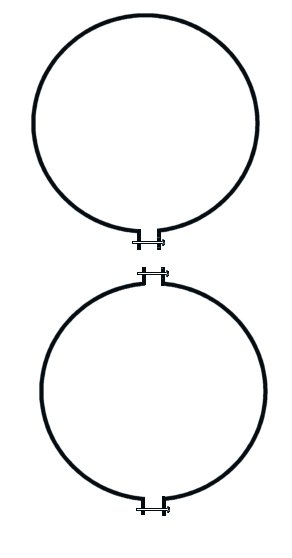
- Meanwhile or at the same time, to make the lid bend a steel band into a loop with the
ends bent back [or 2 half loops to match mine], drilled for a tightening bolt. If you are making one
like mine, opposite the bolt, weld a loop or insert an eye bolt for lifting.
The length of the piece(s) will depend on the diameter. See right image
above of lid hanging from chain.
- Place the band on a surface covered with plastic, prop it up about 1/4"
(6 mm) in three places and form a thin plastic sheet as a bag to be lining
and edge shape - cutting it
2.5 times the diameter of the top. [30" for my 12" lid.] In the center place a Styrofoam
disk or greased tin can to make the vent/access hole.
- Pour in a fairly stiff insulating castable mix, pulling on the thin
plastic to shape it, and pull up the plastic into a bag shape and tie or
twist tie it off so the castable is actually above the band (as well as
below because you propped up the band below. When it has set, cut away
the extra thin plastic, remove the inner core and air dry (the other plastic
will burn off although you can tear it free.) Tighten the band before using.
- Either repeat the process for a back door/plate or make a metal tray
about 1" deep and pour IRC into it to make a base plate. Cover with
plastic to aid setting, then when set, remove the plastic to air dry.
- Assemble the unit, adding the frame, etc. if you wish, and put the
burner in place and gently heat the thing with a candle flame (yellow, low
volume, no blown air) until well heated (over 300F.) Then add air and
bring the burner up to volume for the first full heating.
It has occurred to me today, (2002-01-13) after reading
Dudley's book again, that the fire hole could be a glass melter
for a vertical access furnace! Duh. It could then later be a
small glory hole when a furnace was built.
|
 This
is a
This
is a