Rev. ... 2002-03-21, 2003-02-27, 2004-01-15, 2005-11-21,
-12-05
2006-02-25, 2008-01-26
Return to Sitemap
PIPE SIZES
Copper Working Tools
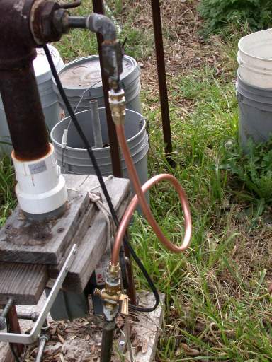
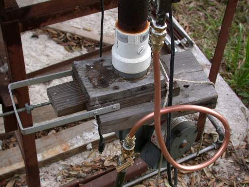
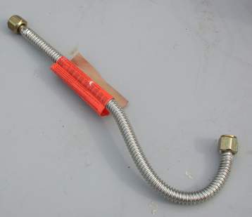
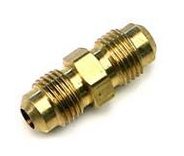
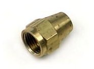
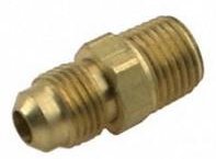
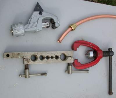
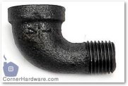
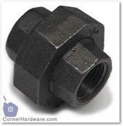
Plumbing for the glass worker primarily involves gas, air, and compressed air, with only a bit of water if really needed. The primary materials for piping these fluids are PVC - a white rigid plastic, copper tubing, and threaded steel pipe, commonly called "black iron pipe." While water can use PVC pipe to great convenience, gas, being flammable, has considerable restrictions against it and compressed air should use the metal connections as PVC has proven dangerous in the higher and changing pressure environments - with reports in woodworking magazines of broken PVC traveling like a rocket across the room to splinter on the other side. Large PVC is commonly used for blower air distribution to burners where the pressure is only a few pounds. The same problems in a fire with gas in plastic occur with gas in metal with soldered joints, thus flared or threaded joints in copper tubing and iron pipe will constitute most connections in a glassblowing studio. For design of plumbing systems as to size of pipe and reductions on branching, see pressure There are two sets of metal fittings that concern the glassblower, those for soft copper tubing and those for black iron pipe. With these two the whole shop can be plumbed, although rigid copper sweat soldered and plastic PVC pipe glued up are options for water. Soft copper tubing can be connected several ways, but flared fittings are appropriate and legal for gas, air, and water. Gas fittings must not be soldered and compression fittings are less common especially for larger tubing used to carry the main gas flow. Shown below are two connectors and the flare nut used to fasten the tubing to the fittings. The right hand image shows a fitting to connect soft copper to pipe threads. The advantage of copper tubing is that it can be formed to make long runs without extra fittings, being bent around corners. The chief downside is that it is soft and can be damaged after installation if stepped on or hit.
|
||||||
|
The tools in these two pictures cost $20-30 and allow working with all sizes of soft copper tubing for applying flare fittings. In the left picture, the grey tool is a small to medium sized cutter with a triangular reamer extended. The tubing is cut by snugging the cutting wheel - on the silver bar, center - against the tubing with knob to the left, tubing being held by the rollers to the right. The tool is rotated around the tubing once and the knob is turned to move the cutting wheel in more. When cut through, the reamer removes the sharp edge forced into the tubing by the pressure. Tubing is flared using the silver bar with counter sunk holes to clamp the tubing - it starts with the end of the tubing even with the surface. The nut must placed on the tubing first. The red tool is placed as shown on the right and the T handle turned to force the cone into the end of the tubing, pushing out the edge to a flare as shown in the left photo (both photos enlarge if double clicked.) | |
Black Iron Pipe
Plumbing connections to my furnace & glory hole were modified and added 2002-03-14ff. Previously, the glory hole had been run off flexible torch hose rated for propane. This was replaced with 3/8" black iron pipe in areas where I will be walking and stepping and with 3/8" copper tubing at the ends to provide a union connection and flexibility in moving the tanks and the burners.
|
||||||||
Copper 3/8" is exactly 3/8" OD. There are actually two different flare fitting threads I could have used, the fine thread being chosen because it is used on flex tubing (see below for limits). Note that soft soldered fittings are not allowed with gas because in the event of a fire, they would melt and release more gas. Tools There are actually several different methods of attaching fittings on copper, including compression and soldering that are not covered here. The tank to right holds 100# or 20 gallons of propane. I own two and swap them. As currently rigged, there are two high pressure regulators on the tank both adjustable, one more easily than the other. The pressure coming out of the tank is about 175 psi, that coming out of the regulators is up to 12 psi. Low pressure gas (natural or propane) is in the area of 6-7 inches of water, which is about 4 ounces per sq. inch (28 inches height difference in a water manometer=1 psi.)
|
||||||||
The connections shown are duplicates for the gloryhole and
furnace. The iron pipes on the right of the picture go down 4 ft.
and cross to the concrete slab at dirt level. They then rise over
the edge of the slab (below) and run around it. The extra elbows
and short nipples keep rain out of the pipes when not connected
and aim the copper fitting in the right direction. A 3/8"
NPT to Flare (Fine) brass adaptor allows connection of the copper. This is the other end of the iron pipe at the glory hole. The pipe ends at a cutoff valve which also adapts to the fine thread copper flare nut. At the other end of the copper, an adaptor and reducer take the 3/8" tubing down to 1/4" NPT for the existing burner piping, which includes a needle valve for volume control. (Burner.htm) (since this picture was taken, the iron elbow was changed to a T and a pressure gauge installed.) Same connection at different angle, showing blower and wood valve. |
![]() |
![]() |
Below is the use of two elbows with a short nipple to turn a corner, rise up from ground level over a slab edge and head off in a new direction that is not 90°. Although not clear, the incoming pipes are entering from the right in the grass. The right elbow is in the glory hole line, the left leading around back (see right) to the furnace. | Street Elbows used to turn a corner with some flexibility, unlike a single 90° elbow at the price of extra space and cost. Here a standard elbow connects to a pipe leading to the tank and turns flow vertically. The street elbow (one female, one male connection) takes the outgoing pipe at the top into the elbow. The joint can be tightened to the correct angle. |
![]() |
![]() |
|
PIPE SIZES - This chart was from A&J Fittings Inc. (before added columns) which no longer shows it. FAMOUS PLUMBING SUPPLY essentially the same table. Note that for the first three pipe sizes, the actual pipe size is more double the nominal.
|
Male threads: Measure the outside diameter of the large portion of the thread at "A"; Find figure nearest this dimension in column 1 or 2 of chart. The dimension in column 3 will be your nominal pipe thread size. |
|||||||
Female Threads: Measure top diameter of thread at "B"; Find figure nearest this dimension in column 1 or 2 of chart. The dimension in column 3 will be your nominal pipe thread size. |
|||||||
Column 1 | Column 2 | Column 3 | Column 4 | Column 5 | |||
OD Approx. (fraction) Inch. for quick reference only | Actual (decimal) Inch. OD |
Circumference See note below on using these columns |
Nominal Pipe Thread Size |
ID | Normal engagement for tight joint (dimension "C") |
Threads per Inch | |
19/64 (3/8-) | .301 | 0.946 | 15/16 | 1/16 | 1/4 | 27 | |
13/32 (3/8+) | .405 | 1.272 | 1 9/32 | 1/8 | 1/4 | 27 | |
35/64 (1/2+) | .540 | 1.696 | 1 11/16 | 1/4 | 0.364 | 3/8 | 18 |
43/64 (5/8+) | .675 | 2.121 | 2 1/8 | 3/8 | 0.493 | 3/8 | 18 |
27/32 (7/8-) | .840 | 2.639 | 2 5/8 | 1/2 | 0.622 | 1/2 | 14 |
1-3/64 (1-1/8-) | 1.050 | 3.299 | 3 5/16 | 3/4 | 0.824 | 9/16 | 14 |
1-5/16 | 1.315 | 4.131 | 4 1/8 | 1 | 1.049 | 11/16 | 11-1/2 |
1-21/32 (1-5/8+) | 1.660 | 5.215 | 5 7/32 | 1-1/4 | 1.38 | 11/16 | 11-1/2 |
1-29/32 (1-7/8+) | 1.900 | 5.969 | 5 31/32 | 1-1/2 | 1.61 | 11/16 | 11-1/2 |
2-3/8 | 2.375 | 7.461 | 7 15/32 | 2 | 2.047 | 3/4 | 11-1/2 |
These
two columns are the circumference, which can be measured by wrapping a
piece of paper around the pipe, marking the overlap, then flattening the
paper and measuring between the lines. It is Pi (3.14159) times
column 2. ID is computed from actual OD and thickness of Sched. 40 (common) pipe given here. |
What is gallons of water in 100' pipe |
|||
1/2" | 3/4" | 1" | Nominal Pipe Size |
0.633 | 0.824 | 1.049 | Diameter Inside-True |
0.316 | 0.412 | 0.525 | Radius Inside |
0.0999 | 0.1697 | 0.2756 | R squared |
0.313 | 0.533 | 0.866 | Pi R sq. (sq.in.) |
0.002217 | 0.00370 | 0.00601 | sq ft. |
0.2217 | 0.370 | 0.601 | cu.ft in 100 ft. |
7.48 U.S.Gallons in cu.ft | |||
1.63 | 2.77 | 4.499 | gallons |