Rev. ... 2003-03-06, -04-04, -06-24
2004-09-19, 2005-02-05, -02-09, -04-18, -11-11, 2006-11-11, 2007-05-26,
2008-03-27, 2009-01-30 (images), -05-10 (tables), -07-01, 2010-10-12, -10-24
Return to Sitemap
Blow Molds | ||
Cast Iron Blow Molds | Press Molds | Clay Molds |
Golf Split Mold | Sheet Metal Optic | Special Tools |
Metal Molds |
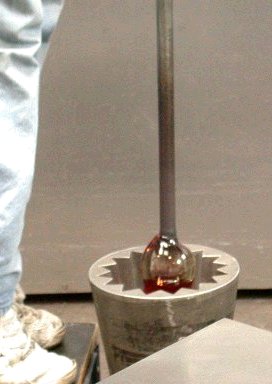
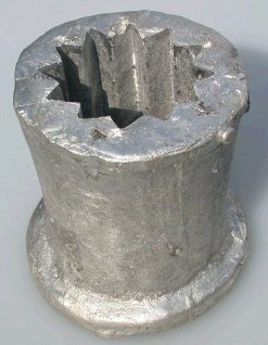
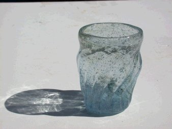
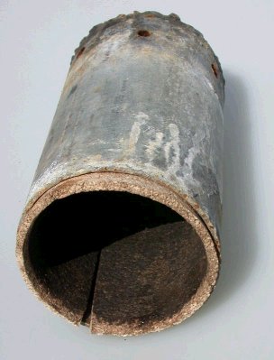
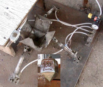
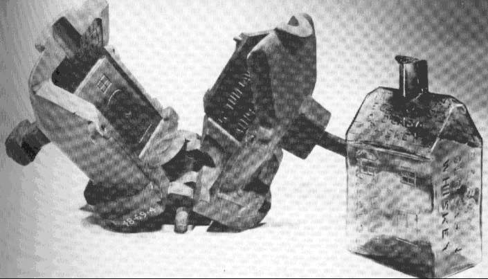
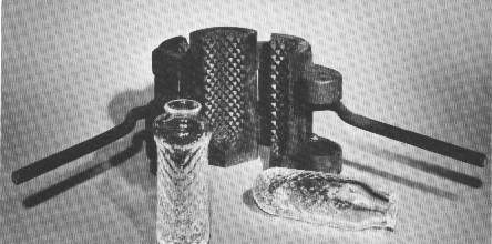
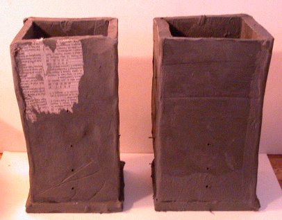
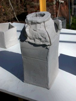
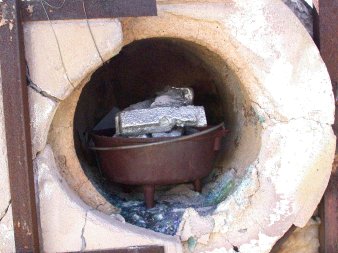
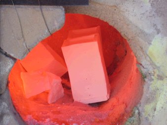
Molds used in art and production glass work fall in four major categories: optics, blow molds, press molds, and special tools. In addition there is a special process that is drawn from solid glass casting where a mold is made from sand by mixing it with water glass (sodium silicate) and hardening it with CO2 (carbon dioxide) - examples I have encountered normally involve a large amount of glass at the bottom with a blown form above that base; the mold is destroyed with each object made. 2010-10-12 This page Glassmaking and Glassmakers Page on the history of bottle making has excellent examples of molds and their results and includes a short video of hand blown bottle making 2007-05-26 Optic molds (or optics) are metal open ended tube molds that form ridges in the outside of the glass. These ridges may be straight lines or diamond patterns, etc. Most optic molds are solid, but those with complex patterns require a hinged split to remove the glass. Jim Moore makes a blade optic in which metal strips in a frame make the grooves. Homemade cast optic below right and rod optic below left. The primary variations in optic molds are: whether the bottom is open - usually meaning straight sided to the mold - or closed - usually meaning the pattern curves from the sides to the bottom, impressing the end of the glass; the number and deepness of the grooves in simple patterns; size; and the design of alternate shapes. A straight groove optic can be used to hold and apply straight stringer. Steinert is a primary purveyor of open optics.
|
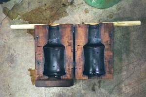
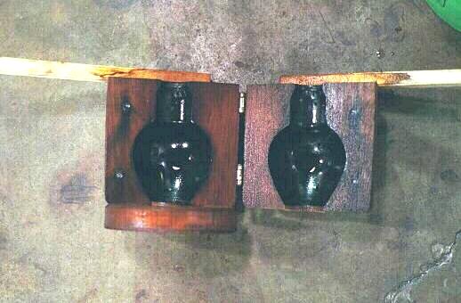
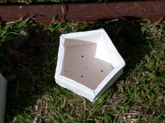
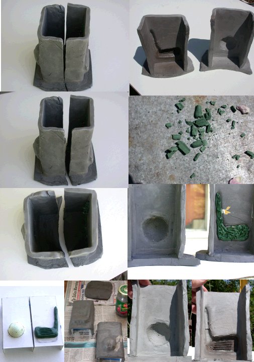
Press molds are used to make pressed glass and are open faced with a matching plug that drives the blob of glass into the mold, also forming the inside of shape. Pressed glass must taper inside to let the plunger out. To allow removal of the glass, multipart exterior molds are used, leaving slight seam lines. Information showing machines from the the early history of mechanically pressed glass is here, although a simple machine to apply leverage has been a part of pressed glass from the start as shown here Special tools may be molds, such as those used to form the necks of bottles. Jim Moore is offering sheet metal fin molds that give a 6 or 8 sided form to the bowl of a goblet when pushed inside the soft glass bowl. 2003-06-24
|
The mold at the right is used by Brad Abrams and was originally cast and built by Steinert then rebuilt locally after a fire. As mentioned above, the blower stands on the platform left and pushes the button on the valve next to the white wood to close the mold through the manifold at the upper right, inflating the glass inside the mold. Lacking dual tubing for double acting and exposed springs, I would guess the recovery springs are internal to the cylinders. The piece made is shown in the insert and is an enlargement of a dradle, normally a small child's Hanukah toy with a shaft on top for spinning on the point - with one Hebrew letter on each side. Besides selling it as an ornament, with a pressed glass base that fits the point, it is sold as a oil candle. Brad is exploring other uses for similar but more flexible equipment. 2005-02-05 |
![]() |
The turn molds at the right are traditional full height
wood mold made of cherry by Walter Evans (who has stopped making
them since the loss of his assistant.) It has a disk bottom
attached to one side and hinges and handles to permit an
assistant to open and close the mold around the glass. The mold
is burned in by blowing glass pieces not intended to keep. It has
holes drilled to allow the steam to escape and is stored in water
between use. The glass is inserted, the halves closed and the
glass allowed to settle near the bottom before blowing and
turning fill the volume. When the glass is removed it has crisp
shape and may require no further work on the body or hot bits for
handles or decoration may be applied. The piece must have the lip
worked. More The Czech blower at the GAS03 Conference used beam clamps on the square wooden mold bodies for handles (Walter's are turned round with a disk at the bottom.) 2003-06-24 |
![]() |
![]() |
Jim Moore is now selling metal "blocks" that are thin cast shells with a cork lining. The material is aluminum per his catalog. [2003-06-24] They are being shown on Olympic Color Rods site, 1" to 10" $40-$60 2002-09-15 The following is a discussion originally posted on the Craftweb Hot Glass site, edited and copied here with permission of the authors.Re: cast iron blow molds
|
Clay Molds
|
A very busy day yesterday. Tried again to do an aluminum sand cast, melting in gloryhole (below) failed. Memo: make mold before melting, don't rush. In the back of the gloryhole fired ceramic clay molds, raising temp after removing aluminum, (lower right) okay, but molds fell apart or cracked at joints. Taken out hot. Poured wax for yet another optic casting, this time with support pins. Blew glass in molds and otherwise - see below. 2005-02-15 |
![]() |
![]() |
![]() |
Well, I did an experimental session and partly succeeded and mostly failed. To the right is the glass from the mold below. The mold cracked at the corners (lower right) and the piece was not properly reheated out of the mold and cracked all over the place while working, but I was able to keep it together for the best image. The far corner visible right through the opening is actually broken open and other cracks circle the bottom and halfway up the flat sides. 2005-02-15 |
![]() |
![]() |
![]() |
The original mold construction plan was built around square bottles and the one at right was blown from the mold lower right. The bottle has a crack across the bottom and up the sides from the punty mark. Of the two molds shown above, the tapered one came apart in the kiln during cool down, below, and the other popped its bottom while blowing. 2005-02-15 |
![]() |
![]() |
![]() |
Below are the three molds from above after gluing them with E-6000. The wiring harness is backup security. Considering what took to take apart glass and metal with E-6000 (850°F not 650°F) 2005-02-15 |
![]() |
|
I built this press (instead of something involving
welding and air cylinders) because of cheapness, materials on hand and
incredible frustration that I could not blow glass for a long period.
[These pictures were taken 2005-09-23, look at the dates above and finally
blowing glass into them below] This montage shows the open and closed
positions. The wires on the clay mold insure they are pulled back.
The cutaway on the vertical support clears the protrusion off the ball/club head
on the mold. The metal angle at the left end is a step-on to open while the
raised section is step-on to close. The left end wood is screwed down, the
right end is held by screws with washers through slots to accommodate different
molds. The only thing I would add is a pair of guides midpoint on the
slider (about where the picture seam is) to keep it from slipping sideways. Big,
awkward, easy to build, easy to use. 2005-11-11
I blew into these molds and recovered a glass piece (below) that shows all the
problems of blowing square and into deep set molds - cracked all over the place
and lost one in the glory hole. The bottom popped off also.
Inclined, in this case, to use a flat plate all the way across the bottom
instead of trying to make matching half plates and firmly attach them. The mold
of the club head, which was originally made in clay came out with better
definition that the golf bowl, which was a real golf ball pushed through a hole
in cardboard. No real dimples at all. Probably protrudes too far but
maybe okay with more practice. 2005-11-11
|
|
Other Techniques
|
Sheet Metal
Molds Stainless sheet metal can be used for dip molds, by folding the sheet to make a deep "cookie cutter" pattern or by making sides and clamping at the corners. The picture shows 3 curved sheets with flange bent back at angle to provide clamping surface while holding the angle of the design. For scale, the clamps are 1" between jaws 2008-03-27 |
![]() |