Building a Sheet Metal Annealer

Virtual Book Annealer Notes 7/28/96 Rev. 2/18/98, 3/18/2000, 2003-01-21, -08-21, -09-07
2004-12-04, 2005-03-10, -12-19, 2007-09-10, 2008-05-29, 2009-03-04, 2011-05-27

Summary Notes followed by detailed discussion of my construction of my small fiber insulated annealer

Background My Building Other Pages
Why Annealer First? ANNEALER BUILDING SECOND ANNEALER
Why Anneal? BUILDING THE BOX Adjustable Large Annealer
What is an Annealer? INSTALL HEATING ELEMENT GLASS GARAGE
What Else in my Annealer? TESTING Doors
BOX CONSTRUCTION-Summary CHANGES I WOULD MAKE Bead Annealer
FIRE BRICK BOX - Summary   Thermocouples
THERMOCOUPLES & THERMOMETERS REFRIGERATOR/FREEZER ANNEALER CONTROLLERS
FIBER BLANKET CONSTRUCTION - Summary SMALL ANNEALER/KILN/OVEN  

Back to Sitemap
Back to Equipment Sequence

Why Build the Annealer First?

  As the next section points out, annealing glass is necessary to save it from cracking.  Therefore, the annealer has to be ready when the first glass is melted if one is to save that first piece of glass for posterity.  In fact, the first piece I blew from my tiny fire brick furnace/glory hole was not saved, because I did not have an annealer or kiln.  It exists as a photograph only.
  In addition, annealers are just variations on fusing kilns, color ovens, and glass garages.  Once one has built one, additional versions, including bigger annealers are just progress.  In fact, an older smaller annealer may become a garage or color oven later.

Why Anneal?

 A brief lecture on annealing, if you will allow me.
 Glass with enough strain it in will break.  It may shatter or it may develop internal cracks which show as silvery paths through the glass (example).  Strain in glass may be due to incompatible glass which is not solved by annealing or by too rapid cooling, which is what annealing solves. (2007-09-10)
 The idea is to get all the stresses that cause fracturing out of the glass by holding the glass at a temperature that will let it "flow" (relieve stress) but not change shape.  This is commonly taken for art glass as 90°F (50°C) below the temp at which a long thin rod supported at the ends just begins to sag when held for 5 minutes at temp, but it is also defined scientifically as the temp that produces a certain viscosity.
  A large piece of glass (an astronomical mirror or large thick cast art piece) may have to be held (soaked) at the annealing temp for days.  A lampworked bead may be flame annealed in a few seconds to produce the same result.
  The next step is to lower the temperature so that no new stress is introduced.  This is where just turning off the kiln or sandwiching the glass in vermiculite or fiber blanket will eventually fail as pieces get thicker.  The physics of annealing requires holding the highest temperature range (say the top 20 degrees, 890-870F for example's sake) for a longer time than one in the middle (say from 720 to 700F).  But the physics of insulation says that the temperature drop (heat loss) will be fastest when the difference is greatest - so the drop from 890 to 870F will be faster than the one from 720 to 700F, just the opposite from what we want.
  Now things might work out with thinner glass, or it may happen that enough time is spent in each range so stress are not too great, but it is a given that failure will eventually occur as glass gets thicker.  When this occurs depends on the amount of glass in the annealer and the construction of the annealer.  An annealer with 100 pounds of glass at 900F takes longer to cool than one with 10 pounds.  Insulating firebrick holds heat in its mass, slowing the fall relative to fiber blanket with the same insulating value (but blanket has a higher value, so 4" of IFB will probably cool faster than 4" of ceramic blanket.)
   So a controller following a straight line or a calculated curve of temperatures  is normally used.  One of the big mirror guys at Arizona has said that he does not use timing at all; he puts thermocouples under the glass (8 meters, 27 feet, across) and keeps the kiln temp 0.5 degree below that; he published in the GAS Journal for 97.
    For the rest of us there are annealing curves and calculations, which can be found in Lundstrom for kiln work, Dunham for lamp and Halem for furnace glass.  The overall goal is to not introduce strain by cooling too quick and not waste energy (or time) keeping the glass warm for too long.

What is an Annealer?

An annealer is a space with a carefully controlled temperature that allows the glass to cool slowly so that strains are released and not re-imposed during cooling. Most annealers used in art glass shops are electric, although they can be gas. Many annealers are built so they can reach a higher temperature than needed for annealing so they can be used for sagging, fusing, and casting. An electric kiln for pottery can be used for annealing, but the control method commonly used for pottery does not work for glass so an additional controller is needed.  Glass can be annealed by moving it through an oven that gets gradually cooler along its length - the oven is then called a lehr and this is the common method in commercial production.

Annealers for glass working consist of five subsystems: the insulated box, the heating element, the timing controller, the power controller, and the power supply. In terms of cost, the timing controller and the power supply may be the most expensive as the former is usually purchased commercially ($200-$800 per kiln) and the latter may have to be done with professional labor (an electrician with permit.) I built mine for under $400, including the $250 cost of the controller.  I did not have to rewire then, but did later.

The box contains the insulation, heating element, and the space for the glass. The heating element is nichrome or Kanthal coiled wire that resists current flow and produces heat. The timing controller contains a clock and electronic or mechanical circuitry to slowly decrease the temperature and usually to measure it. The power controller takes the signals from the timing controller, usually of low level and handles the high power requirements of the heating element. The power supply brings the power from the electric company's connection to the element of the annealer.

It is possible to build an annealer with too much insulation.  The result is that it takes too long to cool down.  While many inches of insulation (say 6" of fiber all a round) may save energy while the annealer is being powered, when the cooling cycle is initiated, at some point, the thick walled annealer will not lose enough heat for the temperature to continue falling rapidly when it should be.  If the controller takes the temperature from 890F to 690 over 4 hours and controls the temp all the way down and it then takes 8 hours for the box to get from 690 to 140, when the lid can be opened without risk of cracking, then there is probably too much insulation. 2003-08-21

What Else in my Annealer?

An annealer is a heated box with careful temperature control.  It can be used for anything lower than its maximum temperature as long as it does not ruin the box for annealing.  The key word there is maximum.  If an annealer is going to be used for activities above normal annealing temp, it must be designed to take those temps.  In particular, nichrome wire is okay at annealing temps (about 900F), but starts sagging and failing faster at higher temps; Kanthal A-1 or equivalent is needed, which means that cheaper clothes dryer elements can not be used.

As long as the annealer will get up to heat, it can be barely heated adequately although a slow recovery can shock glass.  If the annealer is to be used above annealing temp, then the unit will have to be well powered to be efficient and will be very quick to recover at annealing temps.

Problems with doing other things in the box include electrical problems from wax or grease burning inside the box as ovens have ventilation and annealers do not and problems getting moisture out of the insulation if water boils over (or the unit is stored outdoors as mine is.)  If molten glass or aluminum is spilled on a coil element, it will probably cause the element to break. 2004-12-04

 
 Temp Purpose Caution
90F Raising bread, keeping the kiln dry, drying plaster Depending on kiln, covering food may be necessary
220F Melting wax out of investment lost wax castings (over water), heating soup and other foods, boiling water Be sure wax is thoroughly melted out, otherwise smoky burnout may damage kiln.
300F Cooking food, roasting turkey Again, covering food may be necessary
400F Baking bread  
900F Normal annealing, color oven, pre-baking out investment castings  
1040F Garage temp for holding glass for pickup (near sag point) Too hot and it sags, too cold and it cracks when hit with hot bit for pickup.
1200F Art glass sagging, low end  
1300F Aluminum melting, final burnout of investment (1350) Do not spill aluminum (or glass) on heating element, it will probably break the element.
1400F Art glass fusing, low end Providing a view port to see progress without cooling due to opening lid may be good.
1550F High end of window glass fusing, low end of kiln casting  
1650F Other forms of kiln casting, holding point for poured glass casting Poured casting absolutely requires insulated fire brick and top loading annealer.
2000F Melting color for gathering  


Bead Annealer

Bead annealer with slot flaps at bottom of doorBead makers build their beads on a rod mandrel coated with release, normally removing the bead and cleaning the release after the bead has annealed and cooled.  Therefore, it is common for them to use a special annealer which allows the rods to stick out under the door.  The kiln at right is sold by Wale Apparatus and represents a high quality insulating fire brick box.  The front loading door is counter sprung and small flap doors let the handles stick out.  There is a front extension (behind the part number) that supports the rods so they do not tip.  A bead maker will also preheat rods and dry the release by placing rods in, being able to take one out without opening the full door. 2005-12-19

A similar door is occasionally used on a large annealer to allow placing blown pieces while the punty is still attached.  Martin Blank has one for his large solid pieces.


 Very Serious Annealers

When annealers are used in a serious commercial or teaching environment, they are made strong and rugged.  In the past they would have been build with insulating fire brick for the body and floor.  Modern insulation board provides more insulation with a thinner wall, at higher cost.  The weight of the unit is less and is less fragile if it has to be moved any distance. 

Various studios versions of annealers are also shown on my Hot Walls page.  Up to a certain size it is possible to make a box of bent sheet metal, the folds providing the strength.

These two annealers were built in 2006 for the new Tacoma Glassblowing Studio and are provided by Jordan Kube.  The top loading annealer (shown closed and open) uses counter weights attached to steel cables fastened to the front of the lids and up over the black steel frame.  Wooden handles keep heat down.  The insulation board is held in place with studs through the outside metal sheathing and structural support is given by steel angle framing each side.  The heating elements are in the walls so this is for annealing only, not fusing, which needs elements in the lid, especially this big. Three lids provide access with less heat loss and less heat loading on the person placing the stuff.
The front loading annealers on the left also have several doors.  Two units stacked is common.  The doors use a snug down latch like on a semi-trailer.  These are sometimes built so a partition of insulation board can be added and the halves controlled separately. 2006-09-10

Commercial quality annealers

Jordan Kube Member
Registered: Aug 2003 Posts: 238
Re: Your annealer pictures
ok.
quote:
--------------------------------------------------------------------------------
Mike Firth wrote on 09-10-2006 05:37 PM:
I would like permission to post copies of your twl annealer pictures on my page about annealers as examples of high end annealers. I would embed in the picture text identifying the location/source and put similar information in the text next to them.


BOX CONSTRUCTION-Summary

Annealers are of two primary types, those insulated with insulating fire brick and those insulated with ceramic fiber blanket. The former are heavier and more fragile, but perhaps more durable, especially if the annealer is also used for casting where it is raised to 1800.F or more and where molten glass might be spilled, as molten glass dissolves ceramic fiber. Also, depending on the heating element being used, the grooves that can be carved in fire brick provide continuous support for the element, a process shared by ceramic/pottery kilns, which may be familiar to those assisting the glass worker in making the annealer.

Annealers are most commonly front opening or top opening. The latter tend to be somewhat more common due to ease of construction. Front opening annealers tend to be built like refrigerators rather than ovens (side opening rather than bottom opening. Lift up doors are used on smaller annealers.) Front opening tend to be smaller and easier to place small objects into, but may require gloved or tool handling.  With a top loading, many blowers can place a piece while still on the punty and rap it clear.  At least one shop (Wimberley Glass Works) has a front opening annealer placed high enough that a top opening annealer can be rolled underneath it for space saving storage.  When glass is worked in a kiln, it usually is annealed in the same space, but the working requirements may change the shape.  Two variations on special glass kilns are shown below. Two kilns used for forming glass and annealling it.

The upper arrangement is used by a glass artist B.J.Katz at Meltdown Glass Studio in Scottsdale near Phoenix (and others) who uses the large (5 x10 feet) flat deck on wheels to do large sheet work and multiples. The box containing the heating elements is hoisted straight up and down while the waist high deck can be rolled out for access to the glass for setting up or fooling with the hot glass.

The lower drawing is after a photo in Lucartha Kohler's book Glass, An Artist's Medium of a "car kiln at Wheaton Village.".  Here a cart in an L shape is pulled out from a garage shaped housing. The edges must be carefully arranged to provide insulation, but the design is similar to pottery kilns which may use sand to block air flow at the moving edge.  Here the glass is at a low level for working. 2003-01-21
 

FIRE BRICK BOX - Summary

An insulating fire brick box is built dry (no mortar). Normally the first step is to build a platform with a steel plate floor and angle iron edges. Below the platform are built legs and provision for casters. The length and width of the platform are determined by the size of the fire bricks to be used (4.5 x 9" usually) The length of the legs is set by the height of the casters, the thickness of the fire brick floor, the size of the pieces to be annealed., and the convenient height for reaching into the annealer. It is possible to build an annealer with too thick walls so that it will not cool down rapidly enough for the standard cooling curve. Around the outside walls, it is common to use cement board to protect the fragile bricks and refine the form. Sheet metal can be used. The corners of the box are made of angle iron with attachments so that threaded rod can be installed to pull the walls up tight. During construction, the walls are built inside the frame, 4.5" (one brick) being a common thickness. The corners are placed and tightened, pulling the bricks together. The lid is built separately of the same techniques or of fiber, lifted into place, and hinged. A counterweight is virtually always required with a firebrick annealer. To save space, usually this is a weight run vertically behind the annealer with a cable running from the lid up over a pulley and down to the weight. Henry Haven's book Glass Notes has good info on this style in his later editions.

FIBER BLANKET CONSTRUCTION - Summary

Ceramic fiber blanket allows a much lighter construction than insulating fire brick but entails some risks. Ceramic fiber has some of the same risks as asbestos, so it must be handled and used cautiously. Rather than setting the hot glass on the blanket, a kiln shelf may be placed on the bottom. Fiber should not be used for kilns used for poured casting because molten glass will damage the fiber.  Fiber does not hold much heat, therefore it gains temperature fast, but it also loses temperature fast if the lid is held open - insulating (and non-insulating) fire brick holds heat, taking longer to get up to temp and not dropping as quickly.  The kiln shelf or a cast refractory floor, besides providing a firm surface, will slow temperature drop.

Ceramic fiber blanket comes in rolls of various thicknesses and in various temperature ratings. Annealers need only the lowest rating. Typically 100 board feet are in a roll.  This may be 1" thick, 2 feet wide, 50 feet long, the most common, or any combination such as the 2" thick, 4 feet wide, 12.5 feet long in the first roll I bought (at a discount.)  Frax also has a density rating, 4, 6, 8 pound (per cubic foot?) which relates to durability. 

I consider the best construction method to be a pair of sheet metal boxes. These can be made whole at an air conditioning sheet metal shop (where they will be called plenum boxes) or can be bent up in sections. The shape is the same for top and bottom: a large flat section, the sides, and a lip equal to about half the thickness of the insulation. In the lid, the ceramic insulation is stiff enough to stay in place stuffed under the lips all the way around. The bottom is insulated in layers that lock the side layers in place. Water glass is used as glue.

Annealler cross section of lid and box

In this cross section, the stair step effect of the insulation is shown. Cut each piece about 1/2" over length (1/4" long for every foot of length.)  This will stuff the pieces in, making the whole installation stiffer than if some pieces are short. Vertical pieces should also be a bit long, so the lid can come down against them. I added 1/2" insulation on the top of the lower section to pad the lid, act as insulation, and protect the sheet metal from the heat. 6/5/2000, 2003-01-21

Drawing of sheet metal in frax annealer

This drawing shows the basic principle I use: a lip of sheet metal supports the weight while a lining of frax protects the sheet metal from the interior heat (while also insulating the whole box of course!) This works best if the frax is thick enough to remain straight while being stuffed into the sheet metal 1" frax is too thin.


ANNEALER BUILDING

INTRODUCTION - Because I have relatively little money to spend on what is a fairly expensive hobby (at least for now), I decided I needed to gradually build the tools for glassblowing and other glass working as my budget allowed. To stretch my budget and improve my understanding of the basics, I plan to build as much of my equipment as possible.

In looking at my needs, I felt that I would need a annealer if I had anything else, so I needed to build the annealer first. [After the annealer, I expect I will build a grinding/polishing unit, then a glory hole and a furnace. comment ca.1992]

For the annealer, I decided to build a relatively small box with lots of insulation and to build the biggest box I could with one sheet of insulation. I had access to some 2" 1900 blanket at a lower price because it was a return. The smaller box also follows the suggestion of Dudley Giberson in his famous booklet.

The annealer development falls in three parts: Building the box, controlling the electricity, and measuring the temperature. In my case, I did the temperature first, because it was easiest to work out, and involved the most parts buying and least assembly.

Please note that while I am using a sheet metal box, most annealers are made in one of three ways: ceramic board with metal angle corners to hold it together; insulating fire brick with metal corners and framing; and fiber in an existing metal shell. The first is somewhat fragile and should not be moved a lot. The second is more costly and is most often used when the annealer is also used for casting & fusing. In the third case, almost any metal shell can be used, but make sure it is scraped clean (some friges have asphalt paint on the inside) and get help on rating the heating element from Dudley Giberson. Heating elements are not run near their melting point in an annealer (as they are in fusing) and some people use clothes drier replacement elements.
 

THERMOCOUPLES & THERMOMETERS Rev. 7/4/94, 2000, 2002-02-26

A thermocouple is two different metals, usually wire, welded together to produce a pair of junctions. When one junction is heated (or cooled), a voltage is produced and current flows. Any pair of metals will do this (the reaction is part of what causes corrosion), but some do it much better (higher voltage, better linearity.) Because the effect will occur with any metals, care must be taken in wiring and switching thermocouples to avoid introducing additional voltages by creating other junctions.

[A more detailed description has been removed to Thermocouples & RTDs where it has been modified and improved.]

K Type is connected with special yellow (+) and red (-) insulated wire with the metals in the wire matched to metals in the thermocouple and I use a standard mini-connector on my devices that lets me also use commercial thermocouple probes and measuring devices. Type K thermocouples are typically $16-25, connectors $5.50 a pair.

In order to measure temperatures, I looked at analog and digital pyrometers. Analog uses a dial with a moving needle, while digital displays digits (numbers.) I chose digital for convenience and accuracy, since reading most analog displays to closer than ten or twenty degrees is guessing. I looked at dedicated temperature measurement units as well as adapters. I decided to buy an adapter that uses a digital voltmeter for the display.

Costing less than the cheapest digital thermometers, but more than analog, the adapter includes amplification and compensation so the reading in millivolts is equal to temperature and the voltage is read with a cheap voltmeter. I use the adapter with the lowest cost Radio Shack Digital Voltmeter ($17 on sale.) The adapter is by A.W.Sperry and cost $66.67 from Grainger with shipping, [Grainger has since dropped Sperry. Call 800-645-5398 for source.] A single purpose temperature meter is about $110.

The adapter comes with a thin bead K-type probe rated to 1400F, except that the Teflon insulation is only rated to 500F. I started using it for testing (and eventually ruined the insulation) while waiting for more serious thermocouples. If only the tip is touched to 1400F presumably it would work.

Mini K-type connector used with many instruments.Following a suggestion from someone at Spruce Pine Batch, I ordered $8.50 [now $16] K-type probes from A.R.T. Studio Clay Co. Neither Grainger nor A.R.T.  carry K thermocouple wire separately, so I ordered that for $8.50 for 6' from Seattle Pottery Supply. The adapter uses (as do as most digital thermometers) a standard mini-connector, $7 for 2 from Grainger. For a thermocouple to work most accurately, all the wiring and all the connections should match the metals in the thermocouple. That is why special wire and connectors are needed. Wire and connectors are also available from Omega. [a much better source, 1-800-826-6342] http://www.omega.com/pptst/SMPW-CC.html  http://www.omega.com/ppt/pptsc.asp?ref=EXGG_KX_WIRE&Nav=temh07 2008-12-09

WIRING NOTE - Many places mention the need for care in wiring and switching but it takes some digging to understand how much care is needed and why. The why is that the thermocouple effect produces small voltages (21.493 mv is specified for 540C, 44.439 mv for 1080C) so that it is easy to mess up the reading if other voltages are created. Connecting thermocouple wire to copper produces a new junction. How to avoid the problem? Keep all the pairs of new junctions at the same temp. At ultra precise labs, this is done with thermal junction blocks. In more practical situations, it is likely that the left-hand terminals of a switch or relay are not much different in temp than those on the right. So, if thermocouple wire is connected to a switch (copper or alloy) and a junction is created, the reverse junction is created at the output a fraction of an inch away and the effect is canceled. This clearly does not apply if the iron in the thermocouple is connected to copper wire which is then run several feet (or more) and connected to iron wire again. Thus, special connectors and wires are available, but special switches are in short supply.

Now that I have used the adapter, and the least expensive digital voltmeter from Radio Shack, for some time, I have found it stable and reliable. I have compared its readings with cones and other thermometers and checked the reproducibility of the readings.
 

BUILDING THE BOX Rev. 7/4/94, 2/18/98

Having decided to build a relatively small annealer, I set a goal of building a sheet metal box from scratch with thicker insulation. I choose six inches of insulation from a single 50 square foot sheet 2" thick (12.5 feet by 4 feet wide.) I could get the 1900.F sheet at a discount because of a returned order at my local distributor. 

A computer spreadsheet allowed me to play around with the dimensions of the box based on 3 layers. Several combinations are possible. The calculations without waste are not easy because the layers must get smaller as they fit inside each other and should step down in size to avoid thru seams. The spreadsheet is available if people want it. It allows for different numbers of layers and different thicknesses for layers.

Among box shape choices are nearly cubical or long and flat, and variations in between. I felt a longer shape, not too deep, would match with the work I expected to do. After some fooling around, I chose 18" long by 12" wide by 11" deep. This gave about half a square foot of waste with no fractional inch measurements. With 6" inches of insulation the outside dimensions would be 30 x 24 x 23. The lid being 6", the base box would be 17" high. Although I didn't think of it at the time, having one dimension 24" was convenient for cutting. After building the box, I would now make the box height 16.75 inches to provide for more projection of the insulation for sealing. I would also consider making a bigger box.

For the lid to rest on the box there should be matching lips, but the lips could not extend into the opening because the metal would conduct out too much heat and the galvanizing wouldn't take the heat. My solution was to fold in the lid 2" and do a U fold on the box for strength (bending the lip down between the layers. The U fold would require bending the blanket to insert the first layer but that was already the case with the lid.

Originally, my plan was to use equipment at my father-in-law's air conditioning shop to bend up the box. I was going to bend pieces as big as I could and join them with sheet metal screws or pop rivets. I quickly found that my biggest piece was not going to be much bigger than one side unless I wanted to do a lot of hand cutting. Just as I was making my decision, my brother-in-law showed up and proceeded to use standard plenum-making techniques with folded seams using equipment that I would not have tried. I still had to add corner braces and pop rivet some overlaps, which I did after carefully supporting the box so the top was level and matched the lid. Basically, what he built was like the plenum box that goes under a rooftop air conditioner and I have been told at any air conditioning shop could make the lid and base boxes for about $60. [When I priced making two larger lids, I was given estimates from $90-150 for the pair.]

Before installing insulation, I had decide how any needed fittings will be installed. I wanted a handle on the lid so installed bolts with reinforcing washers from the inside. I decided that other handles would serve as guides for the lid, instead of using hinges, and would be held with sheet metal screws from the outside. (Actually, I ended up making a wheeled frame for the thing and used parts of the frame to guide the lid. The box is bulky enough to make an awkward carry when not in the frame.)

I fastened the handle on lid using pre-installed 2" bolts on the centerline. After adding a second nut to raise handle, the bolts would not reach through the wood, so after drilling for the bolt, I countersunk 5/8" diameter to take nut, washer, and nut driver around it. Clearance was still tight, so I used router to cut relief for my hand. Sanded all and installed.

Installed handles/lid guides on sides of box. Cut 1x4 (3 1/2 actual) 4" long. Sanded and rounded, drilled for sheet metal screws; counter sunk for screws on hand for full diameter grip of threads. Handles mounted with 1" above edge to guide lid. The wood burned when lid was not perfectly flat.

My 2 cu.ft. annealler with 4-6" insulation, on stand outdoors
[Later, an open walled roof was built to hold the annealers, blowers when
not being used, and other equipment, cover shown was abandoned.]

LATER: Lid was counter balanced with a concrete block hung from an extension of the handle. A ledge was attached to the side of the box, so that when the lid is opened, it rests on the ledge (still rather than using hinges.) A chain was added to stop the lid after failure of the method of having the block rest on the ground when the lid was open to the right point (so now the lid is not instantly removable.) See notes below on size and other changes that might be made. Most people who counterweight a lid do so with a cable from the front of the lid up over a pulley at the back of the unit and down to a weight. Since the weight provides a constant pull, it is chosen so the weight of the lid when down is greater than the counter weight, the effective weight of the lid decreasing as the lid is raised.  In my final design (below), the weight is pivoted closer to the line of the lid as it is opened and the eyebolt extension actually puts the block directly under the support for a balanced stop. 2004-12-04

Annealler side view showing back shelf vs hinge and counter weight Regular annealer with lid open
Annealler on new stand 2001-09The annealer, mounted on its new welded stand after the wooden one finally gave out after about 9 years outdoors. Same old wheels and axle. To balance the height of the wheels, a small log of garden post is held to the other rail with conduit clamps, so it is flexible to shift, but is picked up when the unit is moved. The S-hook of the counter weight shown in the drawing above is visible in the center top of the picture. 16 gauge sheet metal corners were screwed with self drilling screws to keep the annealer in line on the stand. Added after this picture was taken are two small metal corner braces screwed to the back wall at the top to receive the lid when it is lifted and keep it from falling off. 2001-09-23


CUTTING INSULATION

Tools: chalk line, sharp soft lead pencil (#2), long (8-10") blade knife, aluminum angle, wooden bar and panel Parts: Roll of ceramic insulation, metal box, 30-45 ounces sodium silicate (water glass)

Fiberfrax ceramic insulating blanket (Carborundum) is a pure white material that looks somewhat like dense unbacked fiberglass insulation. It comes rolled, wrapped in paper, in a cardboard box. The usual package is 50 square feet in a roll 2 feet by 25 feet, but mine was 4 feet by 12.5 feet. The material is rated both by density (4, 6 and 8 pounds per cubic foot) and by temperature rating (2000, 2200, 2400, etc.) It is brittle and, like fiberglass, can easily be cut with almost any knife (or scissors) but should be cut against a wood support as it tears (pulls apart) easily. It is much easier to cut if compressed from above by a guide board or rail against a board or rigid surface.

All the pieces need to be laid out on the insulation sheet. I used a CADD program, but the same thing could be done by cutting out paper to scale to match the pieces and fitting them in an outline of the full sheet of insulation. If using paper, cut it big -- at least 2" to the foot, so the most common sheet pattern will be 4"x50" -- and make a paper scale ruler marked in scale inches. Mark the list of pieces with letter or number ID's and write the ID on each pattern piece. It may help to write the size on each pattern piece also. As the pieces are finally placed, either pencil the outline and ID on the sheet pattern or use rubber cement (which allows latter adjustments) to tack the pieces down.

Unfortunately, while the easiest way to layout this kind of stuff is to put in all the biggest pieces and then work down, to be sure the inside pieces have no seams, they should be laid down first or nearly so. In my case, I fit all the inside pieces and the big easy ones and then fit what was left by cutting most of the middle layer to fit.

Cutting is easier if the lines go all the way across the sheet, but this is not as necessary as it would be with wood, since the knife can cut sharp corners without the kind of splintering that would occur in wood. Wear gloves and a face mask.

The insulation comes rolled with a paper wrapping which can be helpful for sliding the roll around; it is awkward and will tear on rough plywood. Cutting insulation is easy using a long blade like a chef's knife without serrations. Use a piece of plywood for cutting or place a board just under the area of the cut. Support the cut right to the edge of the sheet to avoid tearing. Work outside so the bits from cutting do not hang around a living area. Wear gloves.

Mark the sheet for only a few cuts at a time and make sure it is flat and the edge is not curled. A piece of thin aluminum angle is very useful as it can be placed on the edge so a measuring tape can be pulled from it (the soft edge tends to bend easily.) If the angle is at least as long as the longest cut, it can also be used as a guide for the knife. I found it easier to use a chalk line to mark cuts since writing on the insulation is not easy. For marking measuring points, a soft pencil will make dark marks while the knife will make the beginnings of cuts. If working alone, a weight or board for one end of the chalk line is necessary. Wear gloves.

In my case, all the pieces for the lid came from one end of the roll and were cut first and installed to reduce the size of the roll for further handling. The inside of the lid was painted with sodium silicate and the layers added with additional silicate dabbed on each layer.

Sodium silicate (water glass) is used as a high temperature glue for motor gaskets and for making clay slip. It is clear and very sticky. I found it hard to paint in strokes, as it pulls the insulation, so I daub. Brushes can be cleaned with soap and water. It is available at drug stores ($3.65 for 15 oz) for no good reason I can determine [liquid bandage and preserving eggs, I found out later], but is much cheaper in bulk from ceramic supply places ($4.35-8.75 gallon.) I needed three 15 ounce bottles and would have needed part of another if I had glued the inner-most layer.

After carefully cutting the pieces, I painted the bottom of the box and installed the bottom layer, then painted each wall and installed one layer all the way around. Most of the smallest pieces were at the ends. I then continued around with the second layer, fitting it inside the first after painting the outside layer with silicate. Wear gloves.

I decided that the third and innermost layer was not to be glued, so that I could, if I wished, try the box with 4" of insulation and a bigger inside. To hold the inner layer, I would add more of the nichrome wire and ceramic loops used for holding the heating element. One piece of the inner layer was poorly cut with almost 1" taper; added thin piece for filler at bottom. I also used water glass on top edges for stiffener. [I did, in fact, remove the inner layer, so the box has 4" insulation on the sides and one end. I did this for more space. I have not done any test runs to see whether I can still get up to fusing temperatures as I could with 6".  LATER: No, I could not.  Stops at about 1300F  When the original element broke, I left in in place around the walls and added the new element on the lid. I plug the old one in to go to fusing temp. 20 amps total. 2004-12-04 ]
 

INSTALL HEATING ELEMENT

Parts: 1/2" sheet metal screws, heating element, ceramic donuts, Kanthal A-1 wire  (Like nichrome but higher temp.)

Tools: needle nose pliers with wire cutter, brass tubing, screwdriver to match screws (I use Phillips), 1/8" bit, drill

I bought my element (120 volt, 12 amp), ceramic donuts, and extra Kanthal wire from Dudley Giberson at Joppa Glassworks. (1-603-456- 3569, best time to call 10am ET. www.joppaglass.com) He mentioned the donuts when I called about the element and suggested the method of fastening described below. The donuts have a hole just the size of the coil and a groove around the outside for the support wire. [Another method is to buy quartz tubes either small enough to thread inside the element or large enough to take the element inside. This is more costly but supports the element from sagging, looking neater and taking away the risk from a sagging element  2008-05-29]

The element was delivered as a tight coil with the ends as 12" leads of straight multi-strand twisted Kanthal. The multi-strand reduces the temperature by increasing area and reducing resistance. The coil must be stretched to the length needed, trying to pull evenly (close coils will get hotter than those spaced further apart.)

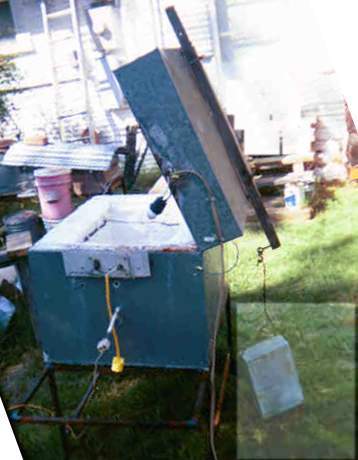
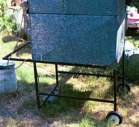
Because I expect to mount my annealer at least part of the time on a wheeled cart that has to go though doorways, I am putting all my wiring at one 24" wide end rather than on the 30" long side.. [After using it for a year, I would put the coils on the lid and the fittings on top. Did this with second coil when first broke [repairs] and now use both elements much of the time for warm glass.] After arranging the coil around the inside of my box and figuring where I wanted support (about every 4"), I threaded all the donuts I needed onto the coil.

At each point where I wanted a support, I drilled a 1/8" hole just over 1" down from the top to clear the folded metal lip. I drilled a second hole 1/2" lower and inserted a sheet metal screw. At first, I straightened the loop of extra Kanthal wire and pushed it through the outer hole and the insulation; several times I had to try again when the wire wandered to one side or down. I think a better technique would be to use the thin brass tube sold for hobbyist use, punching through the insulation with the tube, fitting the wire in the end, guiding the wire as I did with the leads, below. [See notes on heat loss below.]

Inside the box, the end of the wire was wrapped in the groove of the ceramic donut and twisted around itself with needle nose pliers. Outside the box the wire was cut off the coil about 1 1/2" from the wall, bent down while being held with the pliers to keep from twisting the element, and then wrapped around the sheet metal screw which was then tightened. At corners, the supports are placed an inch or more from the inside corners so the coil can curve around the corner.

Alternative 1: Ty Brunson mounts his elements into fiber walls by using pieces of old coil as a screw-in device, straightening one end before installation and bending to make a small hook to hold the element. This would reduce the heat loss to the screws. Ty points out that his method is safer since the element can't connect to the box shell. However, if the box is properly wired, the shell should always be grounded.

Alternative 2: Make hairpin shapes of Kanthal wire and push them into the wool over the wire. This is a bit more fragile and may only work for side walls, not for lids as for fusing. [Actually, it does work for lids, as long as lot of pins are used and the fiber is well glued as I learned from Internet sources.]

The leads for the coil have to be brought out of the box. My first choice was a mistake. I decided to use a piece of wood on the outside as insulator and terminal mount. I screwed the wire to the wood -- it burned.

I changed to a piece of asbestos cement wall shingle and 1/4" brass bolts with several nuts. I first used a long thin Bolts through plate for wire connectionsscrewdriver to make a hole through the insulation, but I could not get the lead to follow it back through. I got a brass tube about 1/8" in diameter from a batch of hobby supplies, used it in place of the screwdriver, placing the lead in the end of the tube to push through. I drilled holes carefully in the shingle to match larger holes in the sheet metal. Outside the box, I carefully bent the Kanthal lead around the bolts to mount it. The wire is stiff and breaks with repeated bending.
[Best: Carve a piece of insulating fire brick to install in a larger hole with drilled holes for wires.  History: Perhaps a better way of getting the coil through the wall, if it is at hand, is to use insulating castable, making a cube with holes and grooves to fit in an appropriate hole in the sheet metal. Soft firebrick could be carved for the same purpose. I expect to do this on my second annealer. 2002-01: Did on lid installation - doesn't get hot enough to set properly and absorbed moisture.] [Used carved insulating fire brick on glass garage and on bottle neck melter and it worked much better. 2008-05-29.]

I prefer a method with no bending at all. This is what split bolts are for: connecting stiff electrical wire. Made of copper, sold at electrical suppliers and some hardware stores, they look like a bolt with the shaft hacksawed lengthwise. The wires are placed in the slot and the nut tightened. Since the heating wire gets hot, Drew Ebelhare in Houston uses 2 sets of split bolts: the first set connect the heating wire to about 6" of very heavy (8-10-12 gauge) bare copper wire and the second set connects the bare wire to insulated wiring to the controller. The bare wire brings the temperature down so the insulation won't melt on the covered wire. Equipment at Texas Tech's Junction Center uses a piece of soft fire brick as insulator to bring the coils through the wall; the brick is mounted in a relatively large hole in the sheet metal shell of the former freezer.

Please note that not mentioned in this paragraph is grounding the shell of the annealer. The connection is not heated, so it can be ordinary wire, but please make the connection. All metal parts of the annealer should be connected together and connected to electrical ground. It may save your life.

The exposed wiring coming out of the annealer must be covered to protect it from probing fingers. Since the connections are fairly warm, it is best if ventilation is provided. Aluminum or galvanized sheet metal can be bent to an open box shape, drilled for ventilation and wire access and screwed to the side of annealer. I prefer to use hardware cloth, which looks like screening with oversized holes and is sold by the foot at (ta, ta!) hardware stores. The 1/4" grid is stiff enough to hold shape, gives superb ventilation and is small enough to be safe for fingers and will ground wires or probes while giving good visibility to connections.

TESTING

I applied power to the kiln for the first time using a Variac (variable transformer.) While my Variac is rated 8 amps, when I started its fuse was 5 amp, so I went to 40 volts which gave 435.F. Cooled from 466 to 250 in 25 minutes. Element resistance is 10.5 ohm. Soaked the kiln/annealer for well over an hour at 40 volts and temperature got stable at 590..

After getting 7.5 amp fuses, and still waiting for heavier thermocouples, I was tempted to put in a piece of glass and run it up to 70 volts to see what happens without knowing temperature. Tried the experiment and burned the terminal screws out of the wood. [See above.] I called Giberson to ask what he used. He said to use an asbestos plate (if one can be found), with brass 1/4" bolts. One nut ties the Kanthal to the bolt tightly. Another is stacked for the copper connection. He suggests mounting the plate about 1" from the wall of the kiln and covering with a wire grill for protection. I bought the brass bolts and nuts and found a piece of asbestos cement shingle to mount them.

During testing the bolts only heat up to 90.F, instead of previous wood burning temperature. However, the mounting wires/screw heads for the Kanthal coil get up over two hundred, which is a real heat drain (and risky to fingers and arms.)

Badly damaged the thermocouple probe testing the heat. It was 870. indicated when I tried to get it out. Pulled the insulation up along the wires. Seems okay on air temp, but jumps around as wires touch.

The K type thermocouples arrived from A.R.T. Clay Studio and I installed one using ordinary copper connection wire. A test is running now, up to 73.5 volts. I am not sure how far off the system is with it. Indicated temperature was 1161 with digital indicated voltage at 76.3 (showing 72 on analog) and resistance 
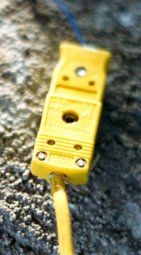
was 10.7 ohms digital. The mini-K connectors arrived from Grainger and their packaging gives the color code.

On a mini connector, the Alumel (red) wire is connected to the minus (-) and the Chromel (yellow) to the plus (+) terminal. Do not solder. Connector takes up to 20 gauge wire.

Considerable overheat at 100 volts on triac testing, up into 1500. range. Outside temperature on box was nearly 200. Plastic tray under measuring devices sitting on lid started to warp.
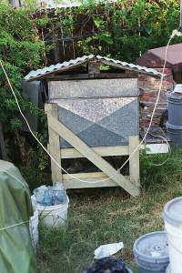
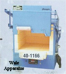
 

CHANGES I WOULD MAKE

After construction, I realized the box should have been a bit shorter (16.75") so more of the liner would project for sealing. I think considerable heat loss occurs through the wires screwed to the metal outside of the case. I will experiment with cutting the Kanthal and hooking the two pieces to break the heat flow and with using stainless steel wire that conducts heat less. [On one test point, this didn't make much difference. Some people hook the element into the insulation, using wire like hair pins.] The annealer does not have a viewing port, a problem I haven't solved yet. An annealer doesn't really need one, but it is needed for sagging glass.

I decided that I wanted a harder floor without yet committing myself to treating the ceramic fiber, so I bought a rectangular kiln shelf. Found that the kiln shelf I bought was too long. Used cold chisel to mark a line and then masonry hammer to break free. Should have cut deeper as break didn't follow line at end. Kept pieces. Successfully used kiln wash from Paragon for fusing.

7/19/92 I have seen glass blowing places that use old freezers and refrigerators as annealers. I have seen furnaces based on experience that end up holding 200 pounds of glass. But I have missed any discussion of how they fit together. Maybe I just missed the right book or article.

A annealer has to hold the results of a day of glass blowing, unless something tricky is going on and two annealers are needed for a day's work, but that can wait. If the pieces of glass is are less than half an inch thick, then one rule I have seen calls for 11 hours of cooling. Paper weights and thicker pieces need longer (by my own experience.) Thus if blowing is to occur every day, with some thicker pieces, there probably have to be at least two annealers.

Based on observation of a beginning glass class, a single blower working a very long day can apparently use about 50-80 pounds of glass a day.

---- After holding the piece in the annealing range for at least an hour, then cool at 20.F each 7 minutes (up to 1/4") to 12 minutes (Complete Book of Creative Glass Art) to 650 degrees and then cooling may be faster to room temperature. 20. each 10 minutes from 950 to 600 would take 2.9 hours after the 1 hour. Cooling at 50. each ten minutes from 600 to 100 (if possible) would take 1.67 hours.

REFRIGERATOR/FREEZER ANNEALER

Most of the frig type annealers I have seen had the thicker arched lid from when they used fiberglass or rock wool inside. Some of these can be used directly for annealers.  Modern thin flat wall freezers and refrigerators use a foam plastic insulation with plastic inner walls. For the reasons given below, I recommend caution in using these for metal shells; they can not be used without stripping.
While walking home from the grocery store tonight (11/10/95), I spotted a modest refrigerator at the curb. Although bigger than my planned annealer (and a different shape) it will provide a quick solution to what has dragged on too long in making the shell. If it proves unsuitable in any way, at least I will have had the experience of stripping one.
To punctuate closing the year, I decided to clean the last of the trash foam out of the refrigerator annealer. I see, in looking back at the issue that while I put a lot of notes into a Recipe on making the annealer, I didn't put much here. I found that if my frig had had Freon in it and I wanted to be responsible, it would have cost $75-100 to get a service company out to drain the thing.  12/4/95
Having stripped one of these out for just this purpose, I will never do it again. I went back and looked at notes on the web site and the pain and nuisance is clearly not there hotbit28.htm#TWOMORE
The problem is that modern frigs are made with a metal outer shell and a plastic inner shell which fits inside. Then the space between the two is filled with liquid insulating foam which expands and hardens AND ALSO GLUES THE TWO TOGETHER.
The only efficient way I found was to break off a saber saw blade short enough that the down stroke did not hit the metal and cut the plastic shell into sections about 6" square and then use a long handled scraper to pry the sections off.
Also, the door is too thin to hold enough insulation and requires either a complete rebuild or some design that will hold insulation down inside the opening below the lip.
 [Note: still working on this thing in 2004, insulation on walls not done, getting vermiculite for floor.]
[9 years later, doing final work here annealr2.htm 2005-03-10]


COIL REPAIR

When a coil has been heated, it becomes very brittle.  Attempts to move it while cold or hitting it while hot with molten glass or aluminum will cause it to break.  The ideal and wonderful situation is that you have another coil available and won't lose anything in the kiln if you take it down to replace it.  The reality is that it breaks at a terrible time - like when you have just put your best piece this year in the annealer.
But temporary or even long term fixes of coiled elements are pretty easy.  Clamping just breaks off more pieces, but if you take the coiled ends and inter-hook them, when you turn the power on, you will see a very bright spot where the contact is made and the coils will weld together providing heat.  When my originally installed wall mount element was broken, I did the hook trick and ordered a new element.  But by the time it arrived, I had used the annealer several times, so I installed the new element on the lid, using only one for annealing and both for fusing and sagging glass.  Interconnected power cords control the temperature. I do check to make sure the element continues intact.  2008-05-29

SMALL ANNEALER/KILN/OVEN

Small annealer (click for larger)I made small annealer/oven (right). This one is a metal box with the top joint bent over and sealed with silicone sealant. It is lined with ceramic fiber (commonly called frax.)  The box sits on an insulating castable flat in a metal tray. And is tipped back for access, allowing fusing or sagging. This unit has only 1000 watts, which is enough to sag, not enough to fuse. The heating element is up inside and the element connections and thermocouple are on the back. Since this picture was taken, a little rain roof has been added to protect the connections. [And since then, it was moved under a shed roof.] Unfortunately, both castable and ceramic fiber suck up water better than a sponge, it hardly drains out. It shorts enough current to trip the GFCI, so I have to use another heater to dry the thing. It needs a skirt of sheet metal to drain water away to the side.

See also the glass garage page.

CONTROLLERS

Discussion of controllers has been moved to Control.htm

Back to Site Map
Back to Equipment Sequence

Contact Mike Firth