|
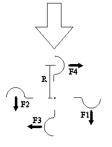
In the image, the wind is blowing from the top. There are four forces applied to the whirly as shown. Each force has its own moment arm R (center of rotation to center of force of the cup.) Of the two drag forces F1 is bigger than F2 (next paragraph) and is usually the only force discussed. But F3 and F4 both act clockwise. Whether they are the same force or different depends on the cup shape (like the lack of symmetry here) and what is in the way (many anemometers have a good sized hub.) 2003-12-31 I learned early that the anemometer cup has totally different
drag when it is open side upwind as opposed to dome side upwind. This is
the Drag Coefficient (Coefficient of Drag, CD or Cd),
[http://www.windpower.org/ Site
still exists, page with data now gone] which is "defined as
the drag force per square meter frontal area of the object."] A round cup open upwind
"has a very high CD of 1.42, whereas its CD is only 0.38 if you turn it 180°
around a vertical axis." For other shapes: "A flat plate has a Cd of 1.28 while a prism
(pointed tail) is 1.14 and a bullet 0.295 which is calculated with the formula
Cd = D / (.5 * r * V^2 * A) where drag (D) is measured in a wind tunnel with
density (r), velocity (V) and area (A) being measured."
http://wright.nasa.gov/airplane/shaped.html eSearch of 'wind
drag of a cone' yields this site
http://www.aerospaceweb.org/question/aerodynamics/q0231.shtml which
has point on ratings down the page of many shapes and discussions of why drag
changes with wind velocity. Also links to other sites. Start of a
history of wind power with some drag discussion
http://www.telosnet.com/wind/early.html 2010-12-11 [Lately I found
While
this difference in drag should be enough to make revolving occur, it does not
explain the better performance of my units with a flange which adds drag, but which should add to
the aerodynamic lift with upstream and downstream (edge on). In the
drawing, which represents the 4 extreme positions of a cup (upwind, downwind,
cup to wind, dome to wind) the two side positions are drag, where the flange
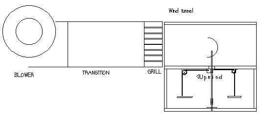
adds to drag equally while the dome has extreme difference as mentioned above. I have a good sized squirrel cage blower that I kept out of the house furnace when we changed it recently - 3 speeds. I had planned on using it to replace the blower from the swamp cooler that is mounted in the garage, but a wind tunnel sounds useful. I went out and wired up the blower to medium and fixed up a switch. Turned it on - lots and lots of wind, maybe too much. The wind tunnel design will be fairly simple - a lead in section with a grid to straighten the air, a test section and a bit of out flow area, perhaps with another grid. The test section has to allow for testing two kinds of force - drag along the air stream and lift across the air stream. If I make the wind tunnel moveable, I could do a blow up or blow down as well as blow sideways. The up or down could make measuring drag easier as it could be straight lifting of a weight instead of around a pulley. It should be square, I guess for repositioning ease. I will continue to explore the Internet and sketch. I have been thinking more about building a wind tunnel. With my usual impulsiveness, I pulled some wood that might make a box, then, with my somewhat less usual reserve, backed off from doing anything without a design. During the day I sketched on a design with a completely different shaped box that focused on solving the measurement and balance devices, which evolved to a square box just for this and the blower and grill attached separately. Also e-mailed Texas A&M about their wind tunnel and usage! [$350/hr] |
|
|
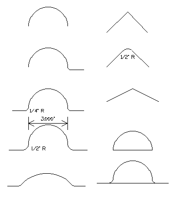 The upwind and downwind positions should be developing thrust (clockwise in this
drawing), but how much? And how does having the cup open or flat across the
opening make a difference?
The upwind and downwind positions should be developing thrust (clockwise in this
drawing), but how much? And how does having the cup open or flat across the
opening make a difference?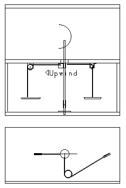
 2004-01-09
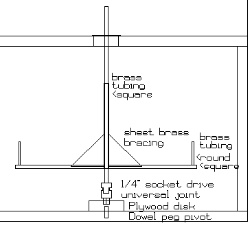
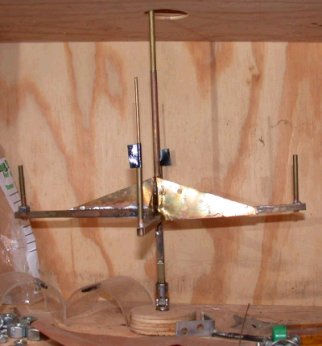
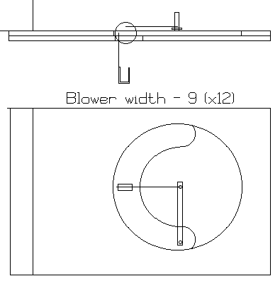
I am continuing by building a basic test bed. Instead of the box above, I
am building a flat plate. The plate has two layers, the upper with a circle cut
free on which are mounted a bar and a pulley. The bar, lower center,
pivots near the edge and supports an upright 532" square tube. On this
tube are to be mounted curved shapes, Plexiglas first, perhaps metal or glass
later. The wind will come from the left. Weight will be placed on
the hook below tied to a string to the center to keep the shape at the center.
By picking up the shape and reversing it, drag in various positions for the same
wind can be tested. The looping C shape is a slot cut in the lower piece
of plywood, which permits the upper disk to be rotated right or left so the
weight can indicate lift, two sides permitting either orientation for
unsymmetrical pieces, like my existing glass. Note that the unit can
not measure drag and lift together or in quick sequence by rotating the piece as
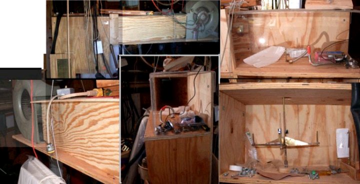
the one above can. [2004-01-15] Ran the wind tunnel for the first time
today, having installed the side and roof panels. Did not try to push in and
reduce wind. The mount is clearly too wobbly and the disk is somewhat off
the centerline. Shows lift, but needs more control and rigidity to be
accurate.
2004-01-09
I am continuing by building a basic test bed. Instead of the box above, I
am building a flat plate. The plate has two layers, the upper with a circle cut
free on which are mounted a bar and a pulley. The bar, lower center,
pivots near the edge and supports an upright 532" square tube. On this
tube are to be mounted curved shapes, Plexiglas first, perhaps metal or glass
later. The wind will come from the left. Weight will be placed on
the hook below tied to a string to the center to keep the shape at the center.
By picking up the shape and reversing it, drag in various positions for the same
wind can be tested. The looping C shape is a slot cut in the lower piece
of plywood, which permits the upper disk to be rotated right or left so the
weight can indicate lift, two sides permitting either orientation for
unsymmetrical pieces, like my existing glass. Note that the unit can
not measure drag and lift together or in quick sequence by rotating the piece as
the one above can. [2004-01-15] Ran the wind tunnel for the first time
today, having installed the side and roof panels. Did not try to push in and
reduce wind. The mount is clearly too wobbly and the disk is somewhat off
the centerline. Shows lift, but needs more control and rigidity to be
accurate.