 |
I was standing in the backyard today
[2004-01-24] and realized that while I had several
whirlies working out there, I had apparently never taken pictures of
some of them.
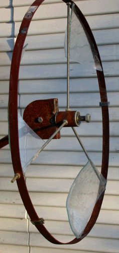
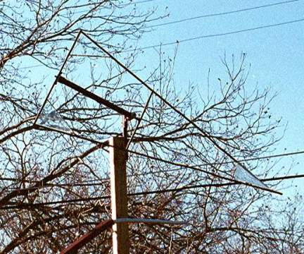
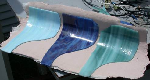
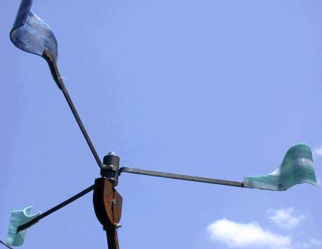
This one is a vertical (obviously) with slumped window glass 'vanes'
glued in place. The vanes are undersized for the thing which is
about 2 feet across, but were made with available width cheap stuff.
This is an exercise in three activities -
drilling, welding and forging a good circle for the rim;
drilling the hub and adjusting the three spokes for balance
slumping and fitting the glass.
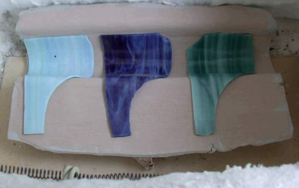
The mold for the glass was made by scooping out damp sand from my
foundry sand box and laying a rolled
out sheet of clay on it. The pattern for cutting the glass and the
clay was shaped of paper to get the corner angle and glass size.
That was copied onto aluminum flashing for a more permanent record.
The slumped pieces (3 runs because of only one mold) were held with
clothes pins while the silicone glue set.
Lead flashing was folded over the rim for balance (lower left and center
right) |
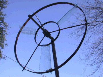
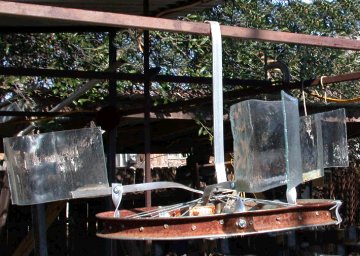
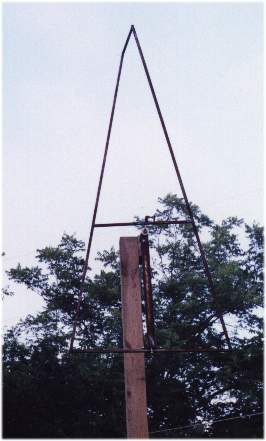
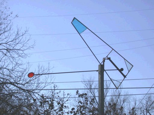
| This is a rebuild of the ring above with
sagged blades more like windmill blades, glued between a 23" outer ring
and the inner with the glass being 7" long tapered 4" to 3" at each end.
The 3 pieces were cut to size and sagged on a clay form. It is
intended that colored glass blades will be inserted between the clear
blades. Turns much more than the one above. 2008-01-14 |
 |
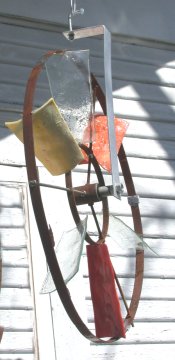 |
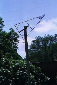
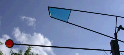
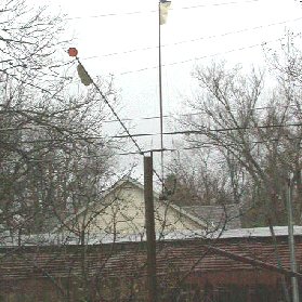
Same frame, with three colored glass vanes added, and a mount to hang it
beside house to it can be seen out window. 2008-03-19 |
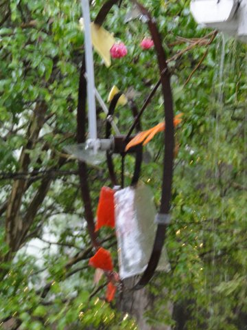
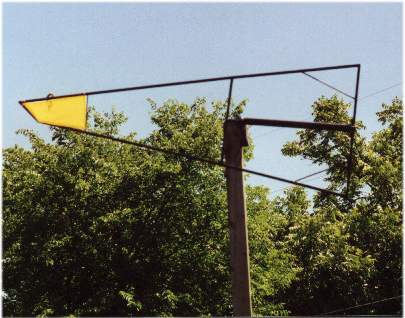
| And this is what remains
of the whirly above, taken during the hail storm 6/13/2012 that destroyed
it and the two flat units above as well as doing $200+ million damage in
narrow swath down through Dallas county. We don't get storms like
this often but when we do people lose roofs and car windshields. And
glass. 2012-06-18 |
 |
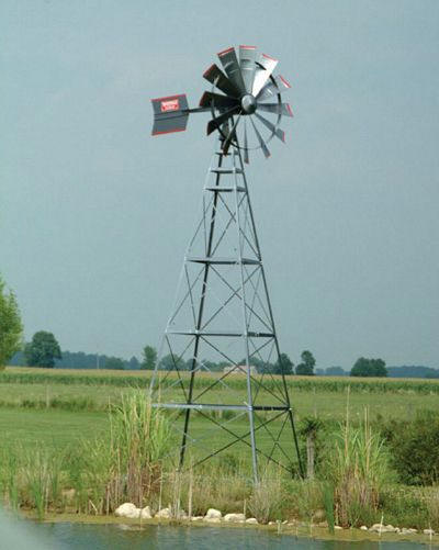
| This image is provided to show an actual
working wind mill (click to link to source site) that pumps air to aerate
a pond. The tapered, twisted curve of the blades can be seen as well as
the outer ring support. Be aware that the decorative windmills sold
in garden centers usually just spin on a fixed shaft, which is simpler to
make, like my whirlies above, but do no work and are hard to adapt to
drive a small generators. 2012-01-28 |
 |
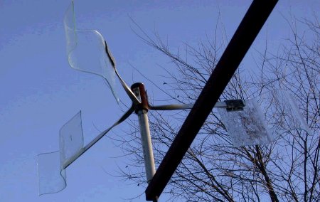
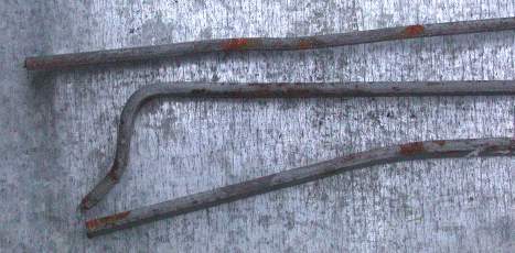
| This is an old bicycle wheel with bent
aluminum bar stock as the mounts and supports for the mounts. Clear
window glass sagged was on a clay form, perhaps the same pieces as below.
An aluminum bar stock bent as a hook at the top and to an offset flat
drilled for the bike axle. With good lube, the wheel moves freely in
the breeze. 2008-01-14 [One glass unit fell off as glue aged
and I just mounted a lead disk to balance and it still turns. 2009-07-30] |
 |
| This is a test piece in a couple of ways. Originally
the glass pieces each had two flanges, but it was very sluggish, so I cut
off one of the flanges, breaking one of the glass vanes. After
slumping a replacement, I mistakenly glued it on reversed (2 down, 1 up).
After it had run for a while, it kept slipping, so I re-bent the aluminum
bar mounts so instead of wrapping around the hub, they were bolted up it.
Works good. |
 |
|
|
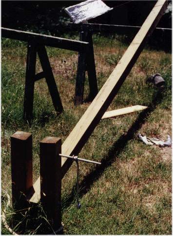
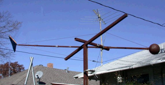
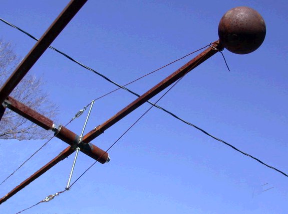
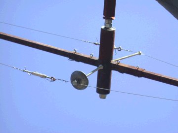
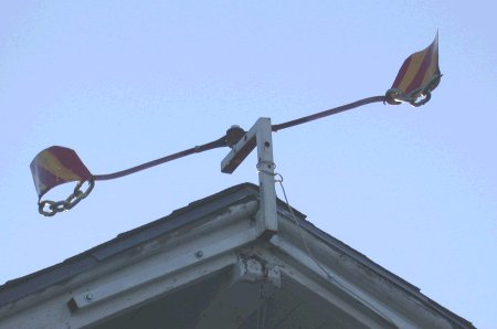
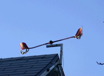
On the front peak of the house, I custom welded and
installed a bracket for mounting whirlies. (Click on pictures to enlarge)
The mount includes wire to send a pulse signal down to the house when
these rotate. There are actually three points on the bracket to
mount 1/2" threaded rod - on top of the top bar as this one is, on
the sides of the top bar, and on the front of the vertical bar. This
whirly is made of sheet metal braised to flat bar stock and was originally
a test to see if bending could be done after braising - yup. The
flat runs on both sided of the hub, held with a 10-24 bolt. The
chain dangling from the sheet metal gives this two vane whirly momentum to
get through the dead spot two vane units have. |
|
|
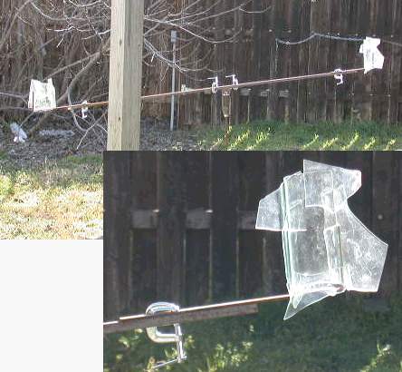
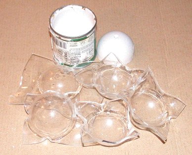
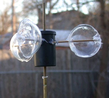
For the wind tunnel,
etc., I needed an anemometer of some kind. This one was made from a
film canister pierced vertically by a brass tube with three brass wires
bent to fit through six holes and around the tube (tricky). The tube
telescopes through a spacer and into another tube to form a bearing
The cups were made by having one half dome plastic cup (not shown) that just fit
in a small mushroom can, so plaster was put in the can, the dome was
pushed in, and the inside of the dome was also filled with plaster.
When set, the dome was removed, leaving two plaster forms with a gap
between. Squares of thin (single weight glazing) Plexiglas were
heated in an oven to about 240F until limp. Using gloves, they were
removed, centered on the plaster dome and the can was pushed down to force
the plex into the dome shape and flatten the corners on the work surface.
As each cooled it was removed and examined - reheating if a redo was
needed. The extra plastic was sawn and sanded off, holes drilled and
silicone adhesive used to glue them on the rods. |
 It moved very
irregularly and drove the birds crazy.
It moved very
irregularly and drove the birds crazy. 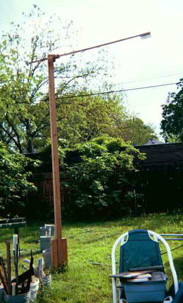

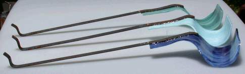
 The
longer super heavy and the older heavy with the round disk, both with metal
fins for greater movement.in heavy wind.
2008-03-18
The
longer super heavy and the older heavy with the round disk, both with metal
fins for greater movement.in heavy wind.
2008-03-18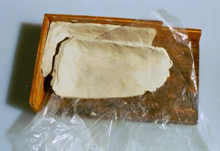
 I have now learned
some of the choices that reduce the size of an animated gif, so here is the
glass 3 arm without saving loading because it is so big. Same post as item at
right.
I have now learned
some of the choices that reduce the size of an animated gif, so here is the
glass 3 arm without saving loading because it is so big. Same post as item at
right. 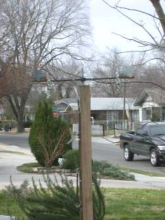

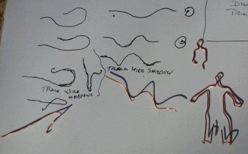 Tailed
Whirl - In
this case,
Tailed
Whirl - In
this case, 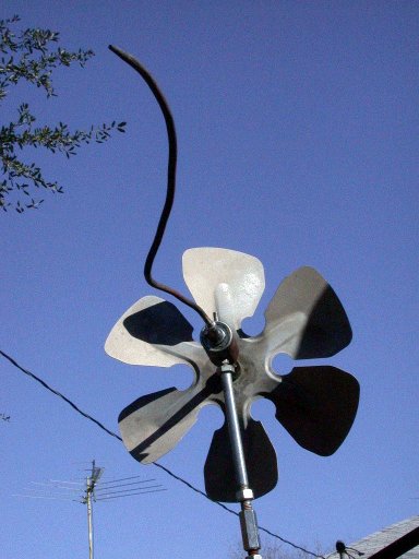