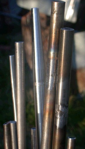
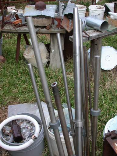
 During a trip north for gravel in a rented pickup, I was near the used steel
place that I get stainless from (Garland Steel) and so I stopped in even
though I didn't have my torch to test. I was looking for solid and
larger tubing to make some more pipes and found marked 304 stainless tubing
and unmarked solid in the same size (5/8") in a shorter 4' piece, so I
took it and it turned out to be not heat conductive. I cut off a 17"
piece of the solid and took it to the Store to use the abrasive chop saw to
cut it to 4" lengths with square ends. During a trip north for gravel in a rented pickup, I was near the used steel
place that I get stainless from (Garland Steel) and so I stopped in even
though I didn't have my torch to test. I was looking for solid and
larger tubing to make some more pipes and found marked 304 stainless tubing
and unmarked solid in the same size (5/8") in a shorter 4' piece, so I
took it and it turned out to be not heat conductive. I cut off a 17"
piece of the solid and took it to the Store to use the abrasive chop saw to
cut it to 4" lengths with square ends.
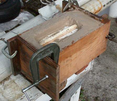
I made a jig to hold the rod upright by drilling in a wood block and
clamped the rod with Vice-Grip pliers to hold it while I end drilled.
I could have center punched, but the holes were okay and since my drill goes
in just over 2", the holes met in the center.
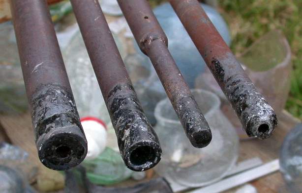
There are normally two choices in ends for blow pipes:
1. An end of the same metal as the pipe but thicker walls and a 1/4-5/16"
(6-7mm) hole and tapering outside is welded to the end
2. A plastic, usually Delrin, mouth piece is fitted to the end usually in
the same kind of metal tube for weight balance..
Most of the comments about knocking teeth out with the metal end have to do
with an assistant kneeling down and blowing into the pipe whipping the head
back and forth while the gaffer works the glass, inflating it against a
block or pad. It is also possible to clang into one's teeth when bringing
the pipe to the mouth but more rarely.
The Delrin Plastic is gentler to the teeth and theoretically more sanitary
if each blower has a separate tip, but almost no one does. The problem for
me is that almost everyone uses their lips to center the pipe when blowing,
but uses their teeth to guide the pipe and keep it from banging the lips
into the teeth so the Delrin gets scarred and chews up the teeth just
rotating when being used in any way. They are supposed to be smoothable with
sandpaper, but I haven't had much luck getting back to original smoothness.
2007-05-09
[If buying tubing, SS comes in very thick walls, so the ends could be made
from tubing with such thick walls as to leave a 1/4" hole (say 3/4" with
1/4" thick walls or 5/8" with 3/16" walls. An alternative if buying
thin and thick wall tubing is to match the ID of the thin wall to the OD of
the thick wall, so the ends slip into the shaft tubing, reducing grinding
but leaving a slight step a few inches from the end. Punties often have such
a step to have a bigger grip on a smaller end, as
here] 2006-10-24 |
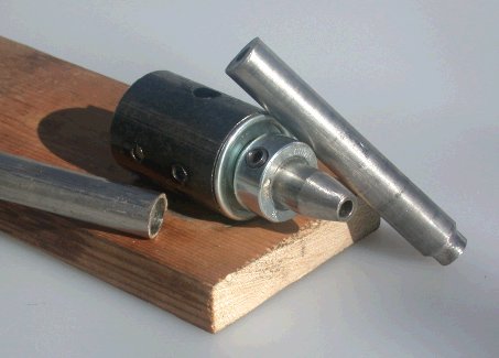
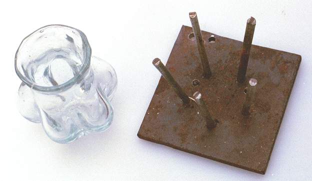
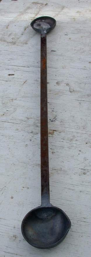
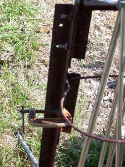
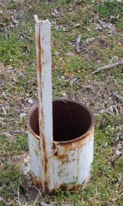
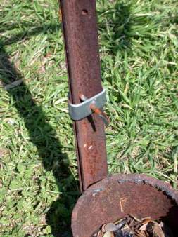
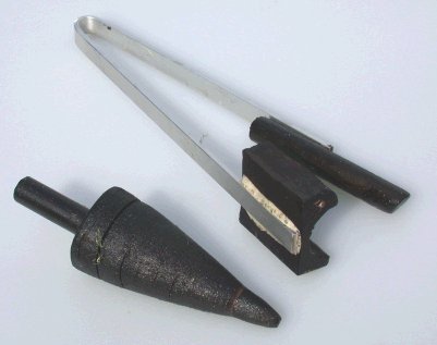
| I chose the ends with the most centered holes to be the
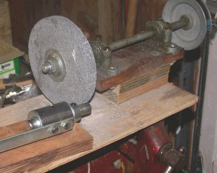
outer end and ground the other ends to fit inside the tubing. In
order to do the grinding, I built the jig shown from 2" of 1-1/2" 16 gauge
tubing, a pair of 1-3/8" x 5/8" ID wheelbarrow replacement bearings, a piece
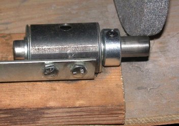
of 1x4 lumber and a 5/8" ID shaft collar. A machine screw bolts the
tubing through the wood to a T-nut accessed with the larger hole on top (the two holes on the side are tapped,
but not used in this version.) The rod slides into the bearing and
almost emerges from the other side; the shaft collar prevents the rod from
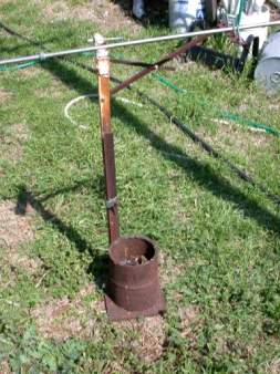
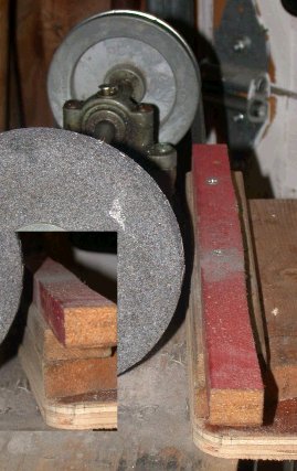
moving further. On my homebuilt grinding wheel head, I added a
platform so I could lay this wood and line up with the wheel. I used a
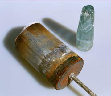
coarse wheel to grind the ends to reduce their size, as shown on the pipe
end at an angle. The hidden end of the other piece looks the same.
I used heavy leather work gloves to control the rate of spin that the
grinder gave to the rod. I tried the reduced end in the pipe as I
worked. The mouth piece was rough ground at an angle and then a finer
grinding wheel was mounted to smooth the outside. 2003-01-19 |
Next, I will weld the ends in place.
I have stainless steel rod and somewhere I have protective flux from
building the ones above, but I confess, I can't recall seeing it for some
time. Torch welding of stainless is less easy than MIG and I am almost
tempted to rent a MIG to try it out. 2003-01-19
After several days of intense searching, which were constructive because
I gained a lot of moving around space in the garage/shop and threw out a
bunch of stuff, I alternated between "logically" looking where chemicals
were kept vs. where welding supplies were kept vs. where glass supplies were
kept. The last proved rewarding because with the grinding grit in the
bottom of a 5 gallon plastic bucket (one of about seventy with stuff in
them) was a rusting can of Solar Flux B for stainless steel, last used to
weld over the tips of a couple of pipes and insert a punty tip.
(above) The rust seemed to go most of the way
through, but the powder inside was dry and fluffy and the instructions
barely readable. I typed them off and visited the web site. "If
you weld stainless steel you'll love Solar Flux" I transferred the
powder to a tough plastic bottle with a copy of the directions.
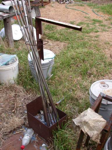
 I got out the threading rig I built and plopped
it on my outdoor work bench, took up the tubing and ends, buttered on the
flux (which is mixed with methanol), fitted the ends carefully, tapping them
to straighten them. The Solar site calls for a carburizing flame (gas
rich) and I found that works well. This stainless does not conduct
heat well, therefore it gets very hot locally very quick. This means the
metal gets molten and flows/drips. The flux helps contain the flow,
but I still had to do some torch repair work and then ground the welds.
Before I put the welding rig up for the night, I cut braces for the glass garage
as it wobbled a bit much and welded them, welded a riser on the frame for
the peak of the roof to hold whirlies and ground down another 4" piece for a
matching punty and welded that in place. 2003-01-30 I got out the threading rig I built and plopped
it on my outdoor work bench, took up the tubing and ends, buttered on the
flux (which is mixed with methanol), fitted the ends carefully, tapping them
to straighten them. The Solar site calls for a carburizing flame (gas
rich) and I found that works well. This stainless does not conduct
heat well, therefore it gets very hot locally very quick. This means the
metal gets molten and flows/drips. The flux helps contain the flow,
but I still had to do some torch repair work and then ground the welds.
Before I put the welding rig up for the night, I cut braces for the glass garage
as it wobbled a bit much and welded them, welded a riser on the frame for
the peak of the roof to hold whirlies and ground down another 4" piece for a
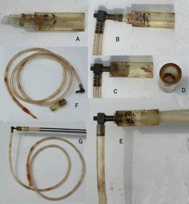
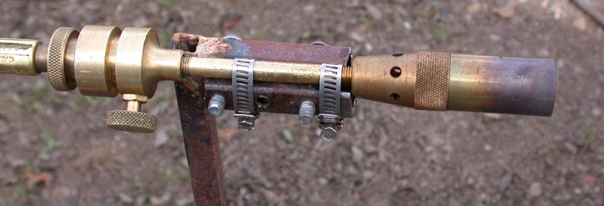
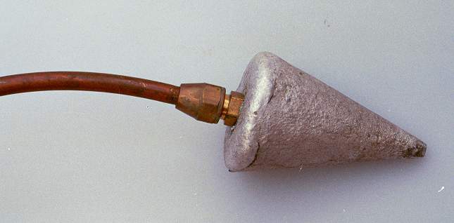
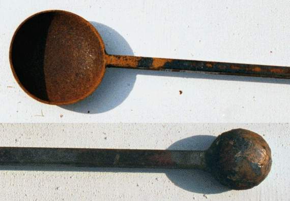
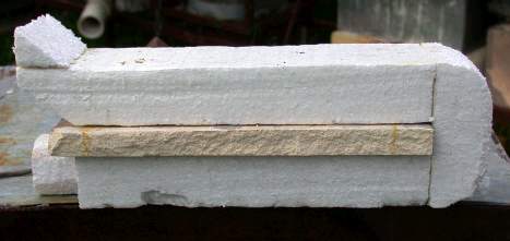
matching punty and welded that in place. 2003-01-30At the right you can
see the moderately rough result of the grinding with no attempt to clean off
the flux, etc. The outer diameter of the pipes is uniform (no bumps)
although some pits remain. I used the pipe and punty for a blowing
session and was pleased with the result. Being careful to make them straight
was important. I shall make at least one more of each, perhaps more.
2003-02-08 I did make another pair of pipe and punty and the welding
on the pipe went particularly poorly. In fact, when ground smooth,
there were holes at both ends that leaked air. Rather than arguing
with the welding, I put the pipe aside until I had some other braising to do
and repaired it with brass, today. 2005-05-13 |
Email Reply on pipes
No, I don't sell (at least at this time). The directions for making pipes
and punties include a way of making without fine machining, but torch
welding SS is difficult.
If you have to deal with minimal purchases (like some SS metal suppliers
want $150 min.) you can use up a minimum real quick with a couple of tubes
of thick wall and thin wall tubing. You can save a lot of money (at $100 a
pipe) and get what you like.
The shaft of pipes is 1/16" wall mostly (.0625") so if you buy 3/4" tubing
with 1/16" wall and with 1/4" wall for the ends. You want 300 series SS,
usually 303, although Steinert
http://www.steinertindustries.com/ uses 309 for the head and 304
for the shaft. See
stainles.htm#SHOP If you want to
make larger shaft punties with largish heads, you can buy some 5/8" solid
which will slide inside the 3/4" tube and be welded without machining.
If you have a TIG or MIG welder, you can do better welding than I can.
If not, talk to a welding shop and see if they can butt weld the tubing.
 If
they can, then the only machining will be to taper the mouth piece. If not,
then the other end of the mouth piece and one end of the hot tip will have
to be reduced by 1/16" (to 5/8" dia) for about 5/8-3/4" to slide fit in the
tubing. Get a quote from a machine shop. See my page above for grinding. If
they can, then the only machining will be to taper the mouth piece. If not,
then the other end of the mouth piece and one end of the hot tip will have
to be reduced by 1/16" (to 5/8" dia) for about 5/8-3/4" to slide fit in the
tubing. Get a quote from a machine shop. See my page above for grinding.
I like 6" pieces for the ends, so the person/shop that tapers the mouth
pieces can saw the thick wall tubing into 24 blanks (assuming a 12' piece
cut slightly short of 6" each). See below on how many get machined. Be sure
understand what you like in the length of a pipe. Many commercial pipes are
52", 54" or longer. Steinert does not mention the length of their pipes but
they do say their punties are 54" I like mine shorter because one technique
I use is to blow down onto a wooden or metal plate and I am 6'2". I
could use a step up. Depending on how the ends are attached, the tubing is
11-12" shorter than the length of the pipe. I would, if paying someone to
weld, make up 2 pipes and 2 punties, and check for balance and length,
before cutting the rest of the tubing. Since I ground my ends, I made 2 pair
at a time. Ask a machine shop about savings on quantity if you are sure of
the size. It may be they can setup and do all 24 slide fits on one end (cut
0.063) for less than doing 4 or 6 at a time. Note that you could do this,
have only a couple tapered and come back to do some more once you were sure
of the fit. You do want the tapered area smooth (almost polished) and you
want the mouth end blunt with a slight curve to take off the corner (i.e.
the final diameter should be about 3/8" so the wall is 1/16" around the 1/4"
hole. see drawing.)
Heck, I've been looking at what I have written and deciding to use it on a
page, so I have taken time to do a drawing.
Please note that I do put a shaft collar on my pipes and punties - the same
distance from the hot end no matter what their overall length for even
hanging in the garage, etc. I do not use a rubber hose grip, which I might
need if making bigger pieces, but that I don't much like. A grip adds weight
(good) to the mouth end and thus affects balance. I do not texture my
grip area (some brands do) but I also do not polish it. I do not like
plastic mouth pieces, I actively favor metal.
Best of luck.
Mike Firth |
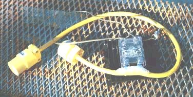
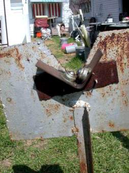
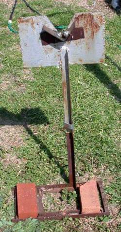
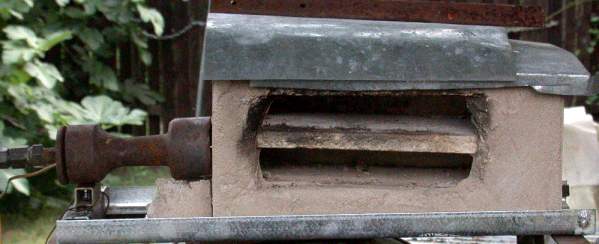
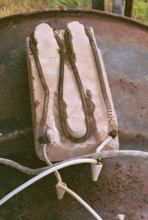 Preheater
for damp glory holes and furnaces - 1000 watt coil set in grooves
in castable. VERY DANGEROUS with exposed 120 volts AC at the
bolts on the front end - should have a wire cage over the
terminals and heating elements. It is only used plugged into a GFCI and is normally moved only when
unplugged while wearing gloves anyway because it is hot. High
temp wiring used for ovens and stoves is attached with porcelain
wire nuts to short pieces of solid copper covered with insulation
tubes to reduce heat load on the insulation.
Preheater
for damp glory holes and furnaces - 1000 watt coil set in grooves
in castable. VERY DANGEROUS with exposed 120 volts AC at the
bolts on the front end - should have a wire cage over the
terminals and heating elements. It is only used plugged into a GFCI and is normally moved only when
unplugged while wearing gloves anyway because it is hot. High
temp wiring used for ovens and stoves is attached with porcelain
wire nuts to short pieces of solid copper covered with insulation
tubes to reduce heat load on the insulation.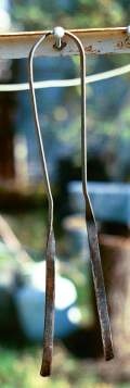
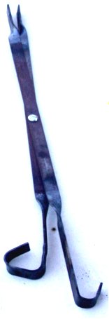
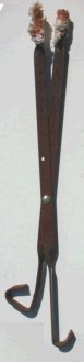
 the
narrowness here means awkward squeezing of the hand can misalign the jacks more
easily. Note that the two blades are twisted opposite of each other. I made one
pair where both had the same pitch and they were more awkward to hold and fit to
the hand. -
the
narrowness here means awkward squeezing of the hand can misalign the jacks more
easily. Note that the two blades are twisted opposite of each other. I made one
pair where both had the same pitch and they were more awkward to hold and fit to
the hand. - 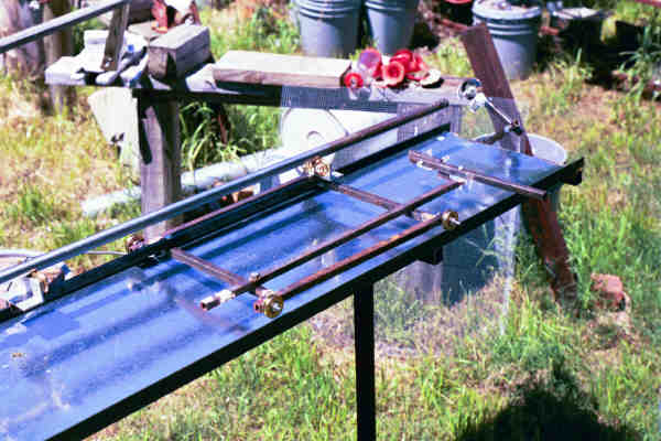
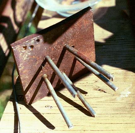
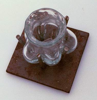
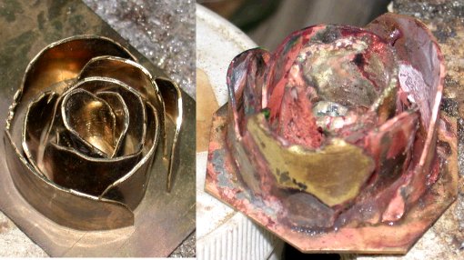
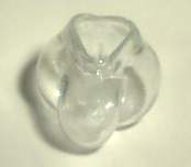 Piece blown in rod optic with three rods.
I like the triangular mouth. Haven't tried equivalent with 5
sided.
Piece blown in rod optic with three rods.
I like the triangular mouth. Haven't tried equivalent with 5
sided.

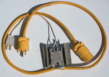 This cable is controlled by 120 VAC so that it can be plugged in to the
indicator light of an element controlled by the one above, allowing control of a
second element from another source instead of rewiring to 20 amp. 2005-05-10
This cable is controlled by 120 VAC so that it can be plugged in to the
indicator light of an element controlled by the one above, allowing control of a
second element from another source instead of rewiring to 20 amp. 2005-05-10


 This drawing shows the revised plan. The dimensions used were selected first to
accommodate the largest diameter I expected to use - 5" - at which point these
dividers will be open at 60 degrees spanning 15.7"
This drawing shows the revised plan. The dimensions used were selected first to
accommodate the largest diameter I expected to use - 5" - at which point these
dividers will be open at 60 degrees spanning 15.7"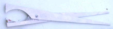
 These
These